| John Broskie's Guide to Tube Circuit Analysis & Design |
| May 23 2026 | Post Number 639 |
||||
Single 6DJ8 40dB Phono Stage
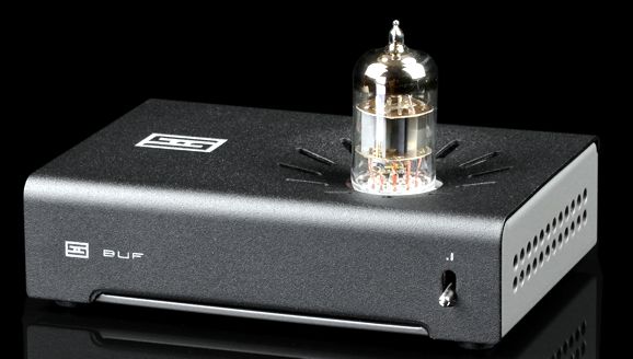
When I first met Jason Stoddard at an RMAF, I asked whether his products were made in China or Taiwan. Neither, was his reply, as they were made in the USA, in California no less! My mind melted. Everyone knew that was impossible due to greater expense and insane government over-regulation—unless, one charged a fortune for the product.
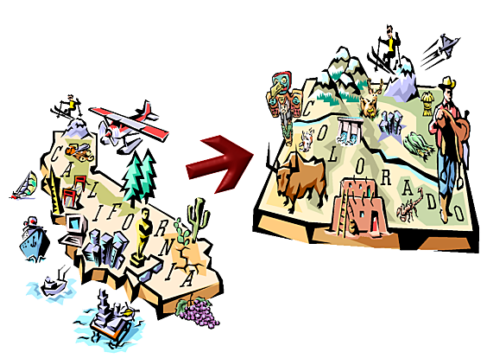
(Sixteen years ago, we fled California, and I spoke to the owner of a machine shop here in Colorado about the cost of their producing right-angle metal tube-socket holders that I could offer to those wanting to build slim-style tube gear. He explained to me that for just the cost of the raw metal in the USA, I could get cut, machined, punched, and anodized finished pieces flown in from China. His business no longer exists; and Colorado is no longer, sadly, the sane alternative to California, as the local headlines proclaim the fleeing of one big company from Colorado to Texas or Florida.) As I was and am so impressed and inspired by the little Schiit Buf, I went searching through my hard drive for a 40dB phono stage that I had designed that used only one tube per channel (only one for mono). I found it and designed a power supply for it that would run off a 12Vac wallwart.
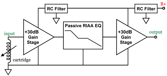
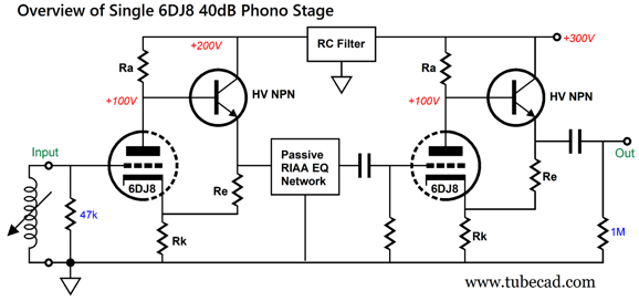
The design uses two gain stage separated by a passive RIAA equalization network. The equalization network steals gain due to its 20dB insertion loss. Thus, in order to get 40dB of gain, each gain stage must deliver 30dB of gain, as 30 -20 + 30 = 40. The problem of limited gain from a low-noise triode, such as the 6DJ8, arises, as the 6DJ8's amplification factor (mu) of around 31 can only be realized by constant-current source loading of its plate, which results in an output impedance roughly equal to its plate resistance (rp). (Roughly, because an unbypassed cathode resistor will greatly increase the plate impedance.) Ideally, the RIAA equalization network should be driven by a low output impedance; and failing that, at least a completely consistent output impedance. My workaround was to use a high-voltage NPN transistor to both buffer the output and to provide positive feedback to increase the gain from the single triode.
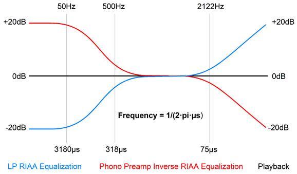
The way the positive feedback works is that in the grounded-cathode amplifier circuit, the triode's cathode is its non-inverting input. Thus, by injecting some of the plate's signal into its cathode, the plate signal increases. Of course, too much positive feedback can easily provoke oscillation, so we must not be too greedy in our hunger for gain. The passive RIAA equalization network undoes the equalization imposed upon the LP.
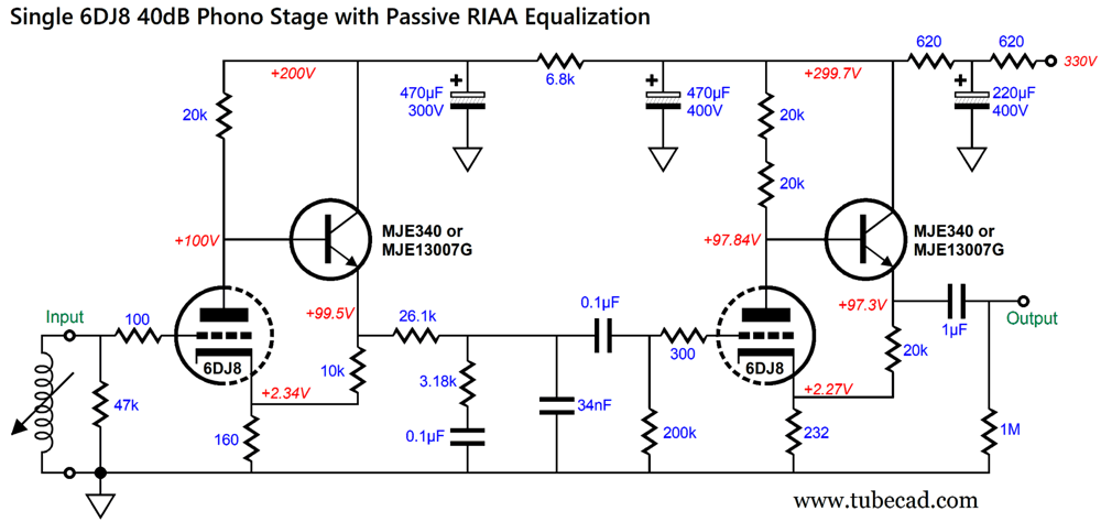
The RC filter scrubs away power-supply noise, but at the cost of a voltage insertion loss. Here is the actual phono-preamp circuit.
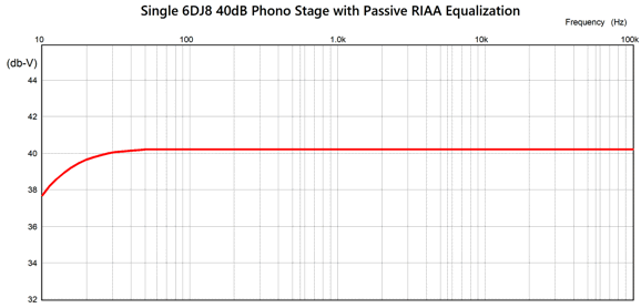
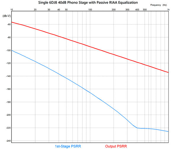
The input triode draws 5mA of current and produces 0.5W of plate dissipation, while its partner NPN transistor draws 10mA and dissipates 1W of heat. In contrast, the output NPN transistor draws 5mA but also dissipates 1W. Both transistors should get a small heatsink, even if it is only a clip on type. I tweaked the RIAA equalization network part values to get to the following SPICE-generated frequency plot.
Where tube-based phono preamp from the 1950s might be so bold as to hold a big, expensive 47µF RC capacitor, this design uses 470µF. New-production tubes might not be as good as those made in the 1950s, but electrolytic capacitors certainly have improved—vastly, in fact. It kills me to see tube gurus slavishly, foolishly abided by the part values from 75 years ago. The reason a 47µF RC capacitor (more likely a 10µF capacitor) was used was due to the 47µF RC capacitor being either unavailable or insanely expensive. There is no audio magic in low-capacitance values. The power supply for this phono preamp uses two transformers, one inside the preamp's enclosure and one external to it inside a wallwart casing. I like flat-pack power transformers, as the primaries and secondary winding do not rest atop of each other, making for far less capacitance coupling between them.
Note how each winding gets its own plastic bobbin. The trick here is that we use one of the secondary windings as the transformer's primary. An input AC voltage of 12Vac leaves the wallwart and enters this winding, which energizes the two primary windings to 120Vac each.
The brother 12Vac winding powers the heater power supply. Each 6DJ8 heater sees 6Vdc, which will extend tube life. In addition, the heater power supply comes up relatively slowly, especially when compared to the 6.3Vac alternative, as the low voltage regulator capacitors charge slowly. Why is this important? A heater element's cold resistance is a fraction of what it is hot, which means that the heater experiences a huge current inrush until it heats up to normal operating temperature. The relatively slow ramp of regulator's DC output voltage eases the current surge. (If we had a tad more heater power-supply voltage to play with, we could configure the LD1084 as a constant-current source, which would certainly limit excessive current flow.) The high-voltage portion of the power supply is handled by the simple bridge rectifier circuit that uses super-fast HER108 high-voltage rectifiers. The three cascading RC filters, further helped by the large capacitor values, produce an exemplary PSRR.
What if we forgo the 12Vac wallwart? I like the cascading transformers, as they further isolate the phono preamp from the wall voltage ugliness, such as RFI and back-fed rectifier noise from light dimmers and switch-mode power supplies. The way they do this is that offer limited bandwidth, which proves to be a feature, not a bug in this application. On the other hand, a flat-pack transformer already offers more isolation than conventional transformer, which stacks the primary and secondary winding atop each other. Here is one possible high-voltage power supply.
In this variation, both rectifier circuits, low voltage and high-voltage, are full-wave types. The heater power supply uses a full-wave center-tapped rectifier topology, which offers one-diode-voltage-drop less rectification voltage loss, which is useful in low voltage power supplies. The high-voltage power supply uses a two-rectifier voltage doubler, which is a full-wave rectifier circuit, appearances to the contrary. In addition, two 470µF/200V capacitors might cost less than one 240µF/400V capacitor, as we must pay a premium on high-voltage capacitors.
Could Schiit produce and sell this phono preamp for only $199? I bet they could (and I would be more than happy if they did). For us mere mortals, on the other hand, the cost of the enclosure, tubes and sockets, PCB, precision capacitors and resistors, flat-pack transformer, RCA jacks, and wallwart would bring us close to the $200 price tag. Would it be worth it? Only listening to it can prove decisive, but I bet it would prove ear-pleasing, as the small injection of positive feedback creates a dynamic, lively sonic signature, much in the same way that a little champagne makes for a sparkling conversation.
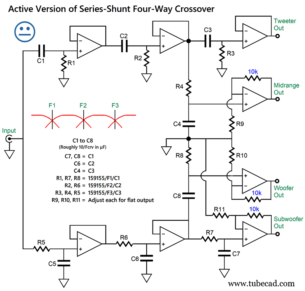
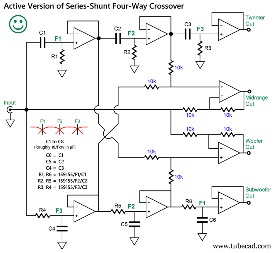
Active Version of Series-Shunt Four-Way Crossover
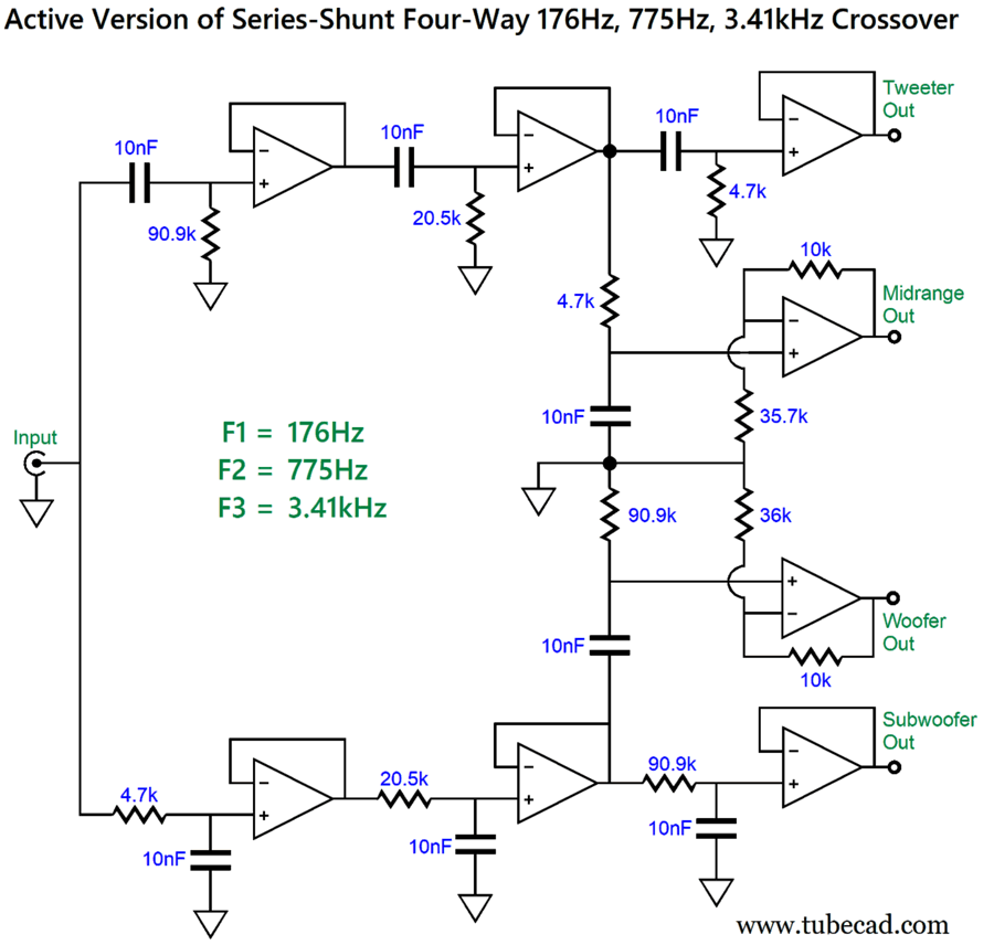
All the capacitors and resistors should be 1% in tolerance. The OpAmps must be unity-gain stable. Note that resistors R9, R10, R11 must be adjusted to deliver a flat output from the four drivers. Here is a design example.
The crossover frequencies evenly divide up the audio of 100Hz to 20kHz. Why not start at 20Hz? I had taken these crossover frequencies from the preexisting passive version, which I had envisioned being used with a subwoofer. Here are the SPICE-generated frequency plots.
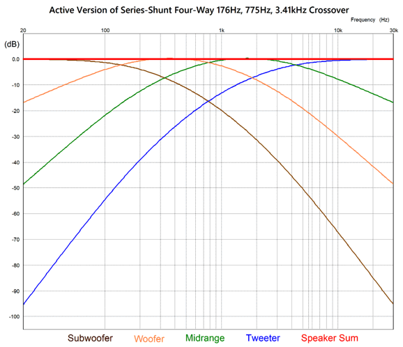
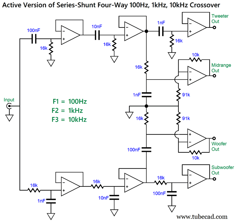
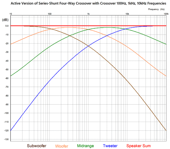
Now, let's compare this crossover to one with 100Hz, 1kHz, and 10kHz crossover frequencies.
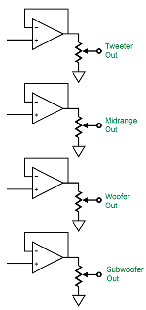
Note that resistors, R9 and R10, differ in value from those in the previous example. The best workaround is to give each output its own output potentiometer, so all four drivers can be leveled in output.
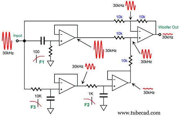
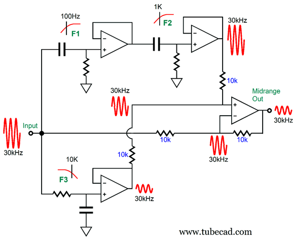
Next, we move on to my recent improved version, which uses only six tight-tolerance capacitors.
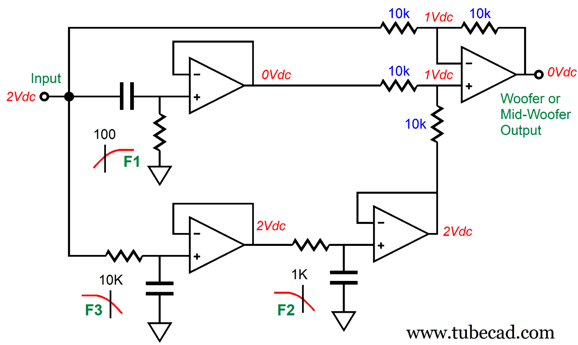
Two differential amplifiers produce the midrange and woofer/midrange driver-woofer outputs. (The eight 10k resistors should be 0.1% types, if possible.) For a design example, let's use 100Hz, 1kHz, and 10kHz crossover frequencies.
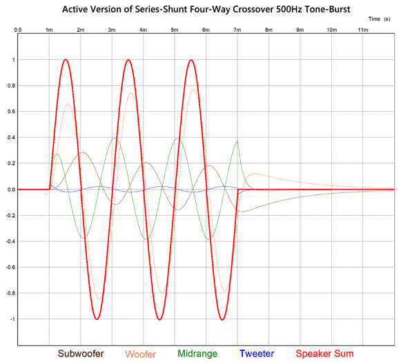
The flat-phase output is vouchsafed by the clean 500Hz tone burst in SPICE simulations:
The summed output delivers a perfect tone-burst of three cycles. This is something that no Linkwitz-Riley or 2nd-order or 3rd-order Butterworth crossover can produce. Since it not enough to pull off an amazing trick, as revealing its secrets is far more useful. To see how the differential amplifier and filters work together, let's look at just the midrange driver-woofer output from 100Hz to 1kHz. We start with a low frequency, very low, as in DC voltage.
The DC voltage cannot be passed by the 100Hz high-pass filter, as the capacitor blocks DC voltages, so its OpAmp's output is 0V. The two low-pass filters in series, however, have no problem passing along the 2Vdc voltage. The rightmost OpAmp's non-inverting input sees the 2V halved, as the two 10k resistors define a two-resistor voltage divider. The OpAmp then strives to develop the exact same voltage at its inverting input, as that is the key feature of an OpAmp. The result is that the only way the two OpAmp inputs can see 1Vdc is if the OpAmp's output is 0V. A low-frequency input signal of 10Hz would see almost the same attenuation. What if the input signal is 300Hz, which is close to the geometric center frequency for 100Hz to 1kHz?
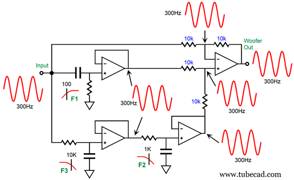
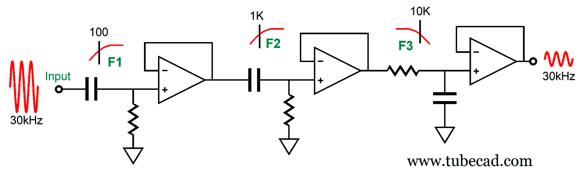
Both the high-pass filter and low-pass filter(s) easily pass the 300Hz. What if we raise the test tone tenfold to 30kHz?
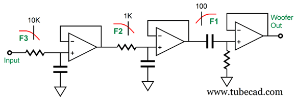
The high-pass filter passes the tone, but the two low-pass filters in series greatly attenuate the signal by -40dB. Thus, the output OpAmp sees the tone almost halved, and the midrange driver-woofer sees -40dB 300Hz signal. What we have here is effectively the following setup:
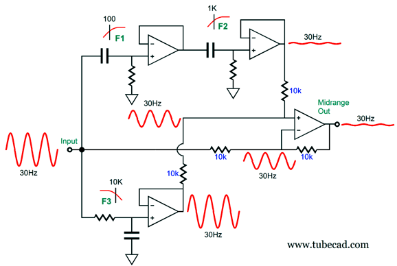
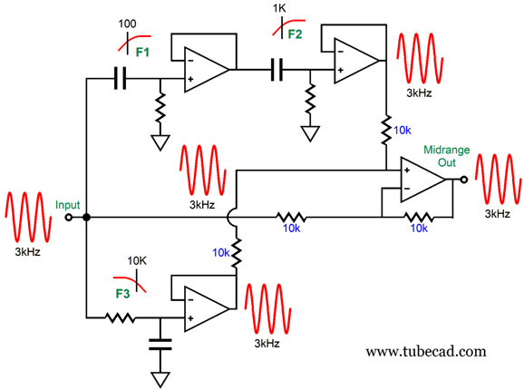
Next, let's look at the midrange output, which also comes out of a differential amplifier and goes from 1kHz to 10kHz. We begin with 30Hz:
The singe low-pass filter passes it unattenuated, while the two cascaded high-pass filters reduce the tone greatly. Effectively, this circuit functions like this one:
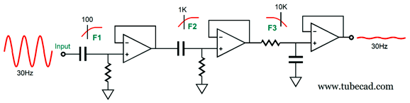
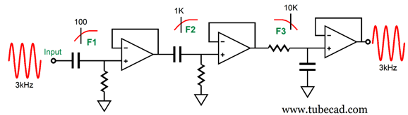
Next, we present a 30kHz tone.
Once again, effectively, this circuit functions like this one:
If the input signal is 3kHz, which is close to the geometric center frequency (316Hz) for 1kHz to 10kHz, we see the following result.
Effectively, this circuit functions like this one:
Few are crazy enough to tri-amp, fewer still are senseless enough to attempt a quad-amp loudspeaker with four power amplifiers and four drivers. Yet, with cost of class-D amplifiers dropping below passive crossover capacitor and inductor prices, we can expect to see many more self-powered loudspeakers. No doubt, most will prove to be dreary, monotonous affairs—at first. But once loudspeaker designers realize that they can break free of passive crossovers and their concomitant limitations, they will seek new approaches. For example, an active crossover can not only cut up the audio spectrum, it can also impose a soft-clipping function and-or driver equalization. Welcome to the future.
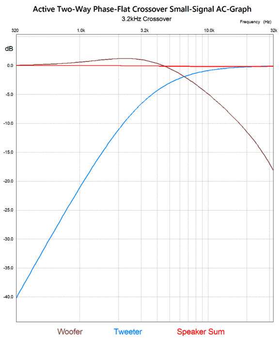
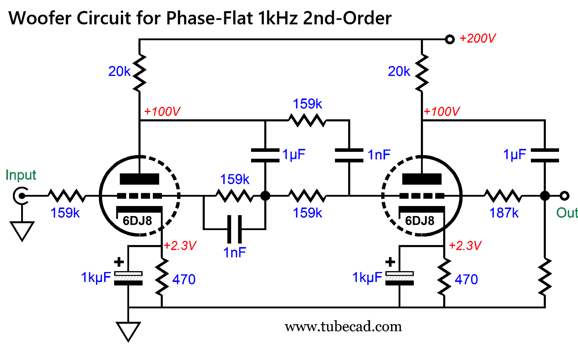
Active Flat-Phase Two-Way Crossover
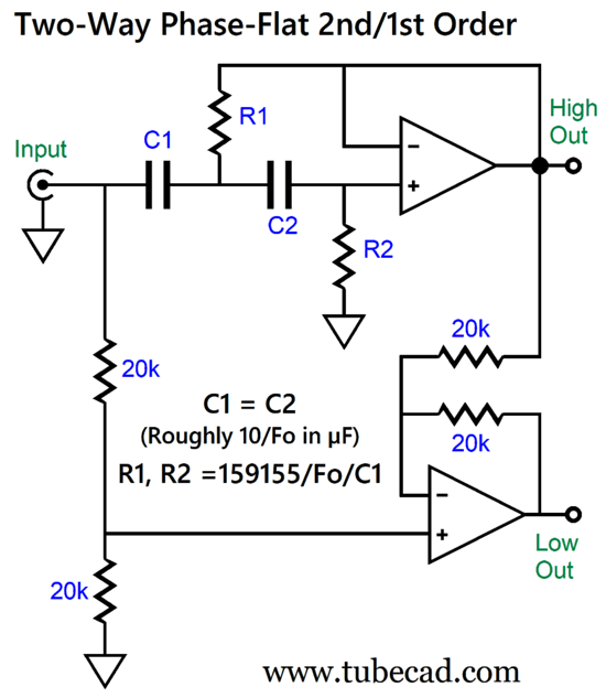
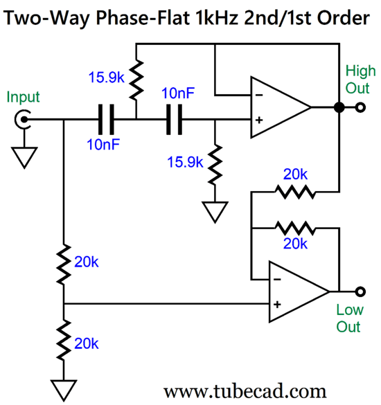
A differential amplifier compares the input signal (halved) to the blend of the 2nd-order high-pass filter's output and its own output, which must undo the high-pass filter's phase shift and departure from frequency flat. Here is a 1kHz crossover frequency design example.
They do not make 1% resistors in a 15.9k value. But they do make 10k and 5.9k resistors, which can be placed in series. On the other hand, most would just opt for 16k resistors, which are readily available and result in a close 994.7Hz crossover frequency. (I won't tell, if you don't tell. Besides, only a few audio reviewers can hear the discrepancy.) What if you do not need the 2nd-order high-pass filter, as your Wiim streamer can deliver 2nd-order high-pass filters with a Q of 0.5? Well, we could just ignore the high-frequency output and use the existing 2nd-order high-pass filter and differential amplifier. True. But is there any other circuit that offers either fewer parts or lends itself more readily to tube translation? This got me thinking. Here was my first stab at a solution:
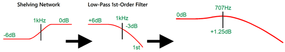
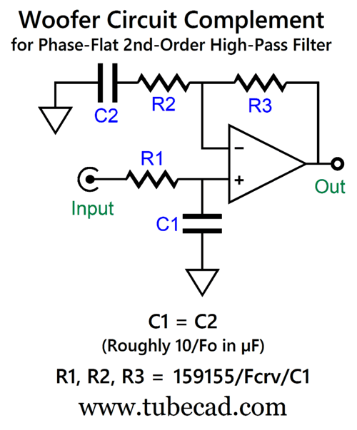
A passive high-frequency shelving network is followed by a low-pass filter tuned to the crossover frequency, while the output OpAmp adds the missing gain of 6dB.
Here is the 1kHz crossover frequency design example.
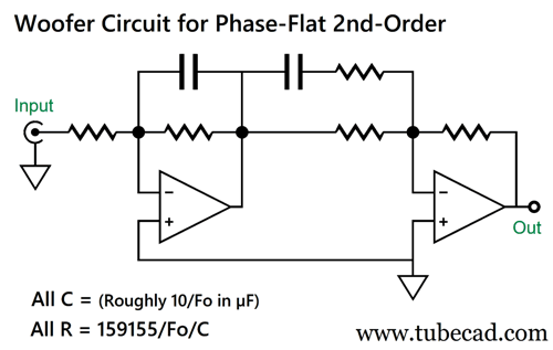
It works, and it offers one fewer resistor, but I do not like that is sensitive to the signal source's output impedance. In addition, the differing resistor values are a pain. Here is my next stab:
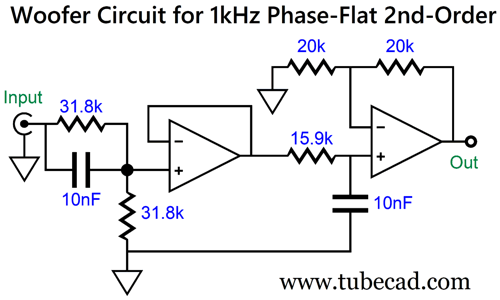
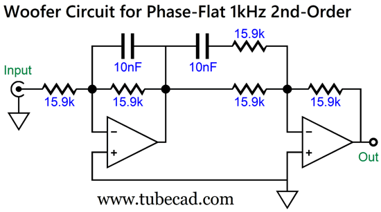
Same part count, but the driving output impedance does not interfere with the crossover frequency.
Note the same resistor value throughout. I decided to translate this topology into tubes.
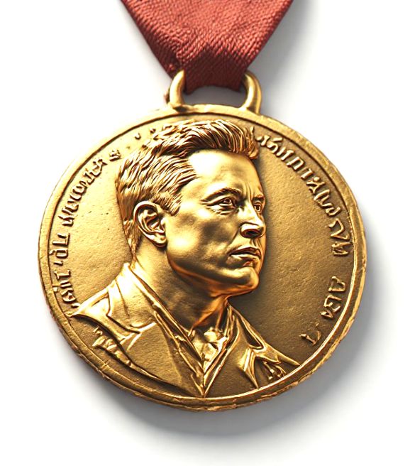
Nice. Where is my Musk Prize? What is that? It doesn't exist, but it should. Much in the same way that Alfred Bernhard Nobel, who sought to atone for having such a dang fine beard, which few men could equal (along with his having invented dynamite) by creating the Nobel Prize, Elon Musk should create the Musk Prize for outstanding engineering accomplishment, in biomedical engineering, chemical engineering, civil engineering, electrical engineering, materials engineering and mechanical engineering. To this list, we should add experimental-physicist engineering, as their engineering wonders allow theoretical physicists to have a job. (Although it would be bad form, Elon deserves a Musk Prize, probably several.) Great feats of engineering often outlast great scientific theories. For example, the Great Pyramids have far outlasted Newton's theory of gravity. We cannot ignore the Great Pyramids or the Eiffel Tower, but it is easy to ignore many hidden engineering triumphs. Who would bring them to our attention? Fellow engineers, much in the same way that fellow scientists bring new discoveries to our attention and that of the Nobel Foundation. Even routine engineering can be a process of discovery and creative solution creation. While some engineers never invent anything and many inventors were not engineers, and while an engineering education aims to instill conformity and conservative practice, the distinction between being an inventor and an engineer can be sometimes small if not nonexistent. It is true that most engineers work in a team, which blurs and hides the role of invention and inventor; but most scientist also work in teams, yet Nobel Prizes are awarded to individual scientists and to teams of scientists not larger than three individuals. Let's be frank: engineers are grossly undervalued by just about everyone, society, media, universities… Often they are viewed as no more than a grim necessity, like dishwashers or accountants. Engineers make things work, often the biggest and most important things, such as airplanes and MRI scanners. Yet, no TV shows or movies exalt them, unlike doctors and cops—even lawyers, lawyers for the sake of God and all that is worthy of praise, lawyers get TV shows and movies devoted to their exploits. (Jackson Browne titled his 1983 album, Lawyers in Love.) What a tragedy this is.
In short, Elon could help make the public, i.e. us, more aware of how much we owe to great engineers and their engineering triumphs. If nothing else, these extraordinary engineers would welcome the solid-gold Musk Prize medal (the Nobel Medal being only gold-plated) and the title of being a Musk Laureate, along with the cool one million—possibly much more, as Elon can do more than just about anyone else, which includes bestowing award funds. Returning to sad and flat reality, I pondered if I could not reduce the part count further. I could:
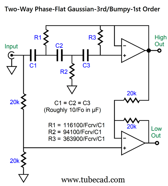
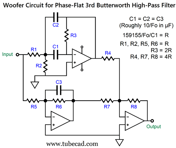
Wow, is that simple or not? The high-frequency shelving network combines with a low-pass filter and uses only one OpAmp. (Maybe, I could be awarded 1.1 Musk Prizes.) I will leave it for the enterprising reader to create the tube-based equivalent circuit.* (A clue: start with the cathode-coupled amplifier.) What if we want to use a 3rd-order high-pass filter? The basic active circuit looks much like the 2nd-order version.
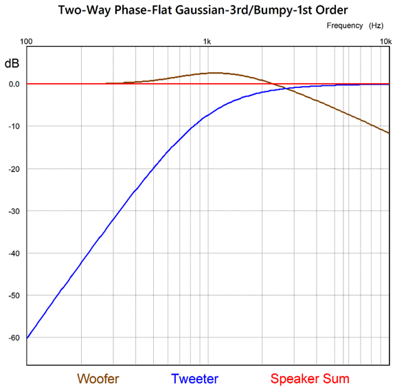
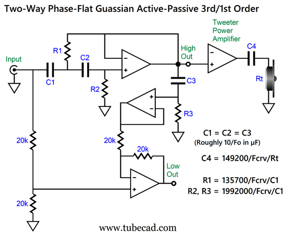
Long-time readers will note that I seem to have a soft spot for the much neglected Gaussian filter alignment. True enough. In this application, it offers a reduced bump from the woofer and reduced tweeter amplitude at the crossover frequency.
Forgive me, but I have to repeat myself now. Bi-amping can be dangerous. How so? If the amplifier that feeds the tweeter loses its connection to ground, the tweeter may go up in smoke due to the full-output 50Hz or 60Hz hum. My workaround is to give the tweeter a crossover capacitor that must be included in the design of the active filter.
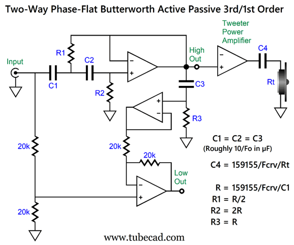
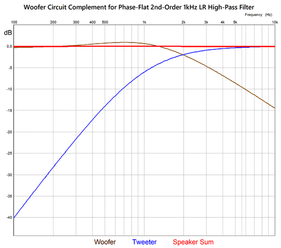
The tweeter is protected from DC offsets and extreme low-frequency signal by the capacitor. (I had to tweak all the part value ratios to get the Gaussian alignment, which explains why capacitor C4's value seems wrong.) Since many have never heard of the Gaussian alignment and generally distrust new things (which raises the question of why they are reading the Tube CAD Journal at all), here is the Butterworth equivalent setup:
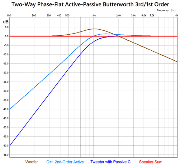
The capacitor C4's value now conforms to the textbook 1st-order crossover value. The active 2nd-order high-pass filter is tuned to the crossover frequency and exhibits a Q of 1, so the effective Q of the combined 3rd-order filter becomes 0.707. The following graph shows what is going on here; note that the dark blue plotline is the combined active and passive slope that delivers a 3rd-order cutoff.
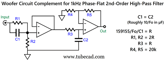
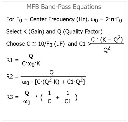
I wondered if I couldn't come up with a circuit for the woofer signal that didn't use a differential amplifier. Why? The translation into a tube-based circuit would prove easier. Here is my circuit.
The math does not get much simpler, the result of using a Q of 1 and a gain of 1 for the MFB band-pass filter. Otherwise, we would have to use the following set of equations.
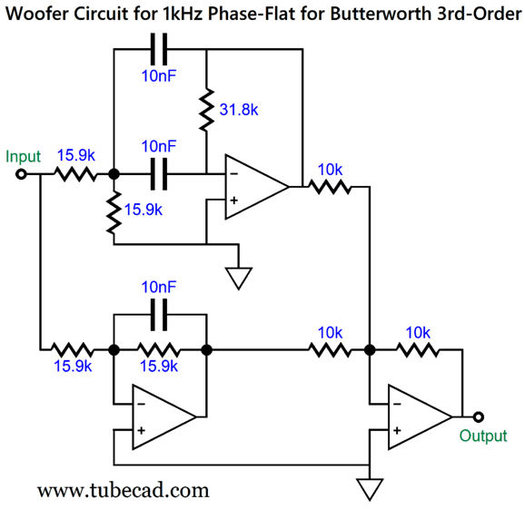
By the way, the output OpAmp is not configured as a differential amplifier, but as a mixer, which is super easy to make with tubes, as all that is needed is a grounded-cathode amplifier with a single triode. Here is the 1kHz design example based on OpAmps.
Okay, that's enough crossovers for now.
A few years ago, I listened to this 2011 album once, and then largely forgot about it. But when I saw it being praised for its high-quality sonic status, I gave it a second listen. Wow! I have added the first track, "Liberty," to my list of great demo tracks. In my web search for more information on this Norwegian singer, I encountered some amazing examples of English prose that were likely translations to English. For example, check out this website, magicvinyldigital.net, where we find the following evaluation of the Dolby Atmos version:
Okay, how much restitution is he or she expected to pay us? At the HighResAudio website, we read:
Of course, we get it. I get it. She can sing. She can produce great albums. And, certainly, such fault finding betrays a petty soul. Still, I had to chuckle—and share. //JRB
Did you enjoy my post? Do you want to see me make it to post 1,000? If so, think about supporting me at Patreon.
Much like the Easter Eggs hidden inside a movie's ending credits, here is a bit more.
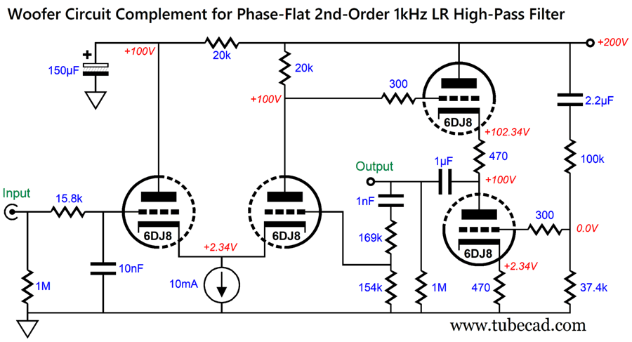
*Answer
The cathode-coupled amplifier provides the non-inverting and inverting signal inputs. The Aikido cathode follower (ACF) delivers the low output impedance and cancels the cathode-coupled amplifier's poor PSRR. The string of the 1nF capacitor and 169k and 154k resistors define the cathode-coupled amplifier's negative-feedback loop. This is certainly more complicated than the original OpAmp version. (Perhaps, I should be awarded 1.2 Musk Prizes.) How well does it work? Here is what SPICE simulation had to say:
AI Summary Assumptions and Approach:
1. Single 6DJ8 40dB Phono Stage Design
2. Active Series-Shunt Four-Way Crossover Designs
3. Active Flat-Phase Two-Way Crossover
4. Engineering Commentary
5. Music Recommendation
Summary: The document provides detailed designs and rationale for a single-tube phono stage and advanced active crossover circuits, emphasizing modern component advantages, practical DIY considerations, and the importance of engineering innovation in audio. It also includes broader reflections on the value of engineering and a music recommendation for audiophiles.
User Guides for GlassWare Software
For those of you who still have old computers running Windows XP (32-bit) or any other Windows 32-bit OS, I have setup the download availability of my old old standards: Tube CAD, SE Amp CAD, and Audio Gadgets. The downloads are at the GlassWare-Yahoo store and the price is only $9.95 for each program. So many have asked that I had to do it. WARNING: THESE THREE PROGRAMS WILL NOT RUN UNDER VISTA 64-Bit or WINDOWS 7, 8, and 10 if the OS is not 32-bit or if it is a 64-bit OS. I do plan on remaking all of these programs into 64-bit versions, but it will be a huge ordeal, as programming requires vast chunks of noise-free time, something very rare with children running about. Ideally, I would love to come out with versions that run on iPads and Android-OS tablets.
|
I know that some readers wish to avoid Patreon, so here is a PayPal button instead. Thanks. John Broskie
John Gives
Special Thanks to the Special 92 To all my patrons, all 92 of them, thank you all again. I want to especially thank
I am truly stunned and appreciative of their support. In addition I want to thank the following patrons:
All of your support makes a big difference. I would love to arrive at the point where creating my posts was my top priority of the day, not something that I have to steal time from other obligations to do. The more support I get, the higher up these posts move up in deserving attention.
If you have been reading my posts, you know that my lifetime goal is reaching post number one thousand. I have 361 more to go. My second goal was to gather 1,000 patrons. Well, that no longer seems possible to me, so I will shoot for a mighty 100 instead. Thus, I have just 8 patrons to go. Help me get there. Thanks.
New URL of the GlassWare website |
||||


| www.tubecad.com Copyright © 1999-2026 GlassWare All Rights Reserved |