| John Broskie's Guide to Tube Circuit Analysis & Design |
| July 28 2026 | Post Number 644 |
||||
Bi-Amp 3-Way Loudspeaker
How does the new active crossover sound? I love it, as the stereo image improved substantially. Alas, it is, like everything else in the world of audio, not perfect. I had been using an active digital 4th-order Linkwitz-Riley crossover at 1kHz. It didn't image nearly as well, but it sure got the relatively sluggish woofer out of the picture quickly, allowing the fast tweeter to shine. Now, the woofer's output extends much further up in frequency, which lends a slight thickening quality to the midrange. The only workaround I can imagine working in my setup is to add a midrange driver, which would be a hassle, as I would have to build another stereo single-ended power amplifier and a three-way active crossover. Bi-amping is a hassle; tri-amping, a potential nightmare. Ideally, I like to go vertical, which means using the same interconnects, same power amplifiers, and same loudspeaker cables throughout. In theory, all nine variables—three different sets of interconnects, three different stereo amplifiers, and three different speaker cables—could be individually chosen for optimal sonic performance. Maybe, they could. More likely, we would get a Frankenstein-like system that would be closer to looking at your backyard through a stained-glass window rather than a single pane of normal window glass, which might not be as clear as we like, but is nonetheless preferable to the many differently-stained chards of glass.
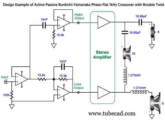
This got me thinking that there must be a way to get away with a three-way loudspeaker system with just bi-amping. Adding a midrange driver would restrict the woofer to lower frequencies, a huge bonus, but how to do it with just two amplifiers? Well, this was relatively easy to imagine, as I had done so before. For example, Post 581 held the following design:
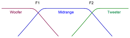
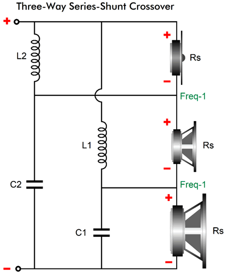
In spite of there being three drivers, this is a two-way speaker, with a single crossover frequency, which in this design example is 1kHz. Also from Post 581:
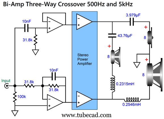
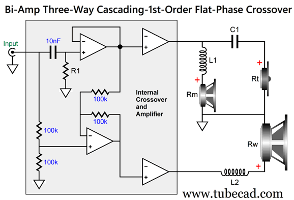
As I looked at the schematic, I wondered if I could not force the design into a proper three-way crossover, one that worked with an 8-ohm woofer. I could. Here is a three-way with crossover frequencies of 500Hz and 5kHz.
Both the woofer and tweeter see cascading filters, so they start off as 1st-order and end as 2nd-order. The midrange driver sees a constant 1st-order bandpass filter. It may look as if we have gained little by using two power amplifiers, as there are still a lot of passive crossover parts. The two inductors, however, are quite small in value—made even smaller once we subtract the woofer's and midrange driver's own series inductance (Le). (Note that the midrange driver crossover parts are not textbook 1st-order values.) This arrangement is the equivalent of my passive series-shunt crossover:
You can readily see that both the woofer's and tweeter's cutoff grows steeper relative to the midrange driver's, which remains a constant 1st-order throughout. It took some head scratching, but I worked out the math required for the midrange driver's capacitor and inductor values. But before going into that, let's look at the overview of what's going on within the active/passive crossover.
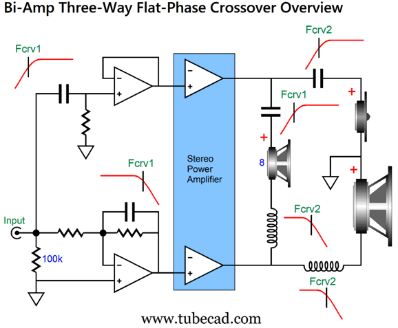
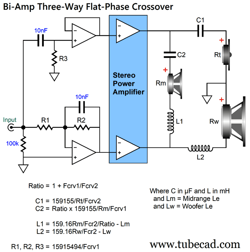
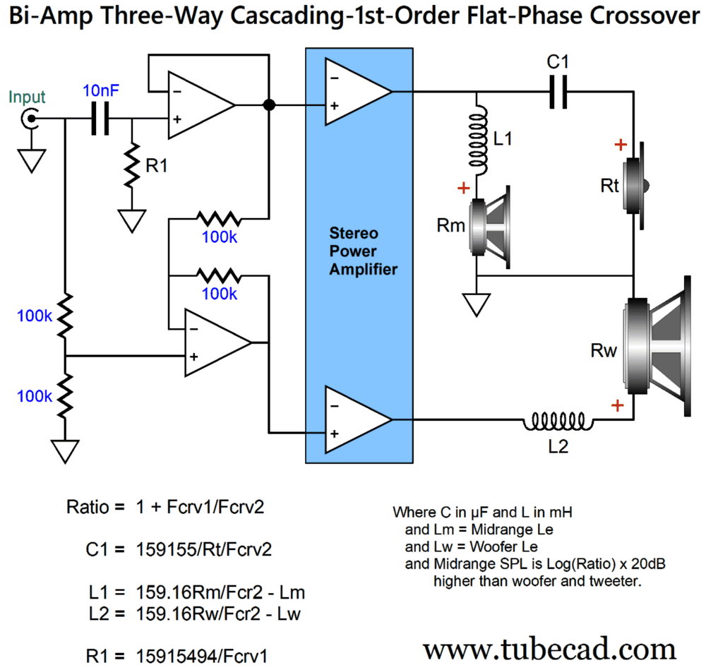
The Lower crossover frequency is Fcrv1; the higher crossover frequency, Fcrv2. The active portion of the crossover is set to just the Fcrv1 frequency. The woofer must be wire out-of-phase relative to the midrange driver and tweeter, as the low-frequency power amplifier gets an inverted input signal from the active low-pass filter; thus, two inversions in series make a non-inversion. The woofer sees two low-pass filters in cascade, whereas the tweeter sees two cascading high-pass filters, while the midrange driver sees one high-pass filter and one low-pass filter, which defines a bandpass filter. Here is the math required.
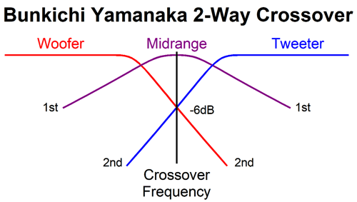
Note the inclusion of the variable "Ratio." This is important, as it is needed to determine the midrange driver's capacitor and inductor values. The greater the spread between the two crossover frequencies, the smaller Ratio becomes along with capacitors C1 and C2 nearing the same value, with inductors L1 and L2 doing the same. At the other extreme, if Fcrv1 and Fcrv2 share the same frequency, the speaker becomes effectively a two-way active-passive Bunkichi-Yamanaka phase-flat 2nd-order crossover:
(Strictly speaking, the midrange driver is labeled a "filler" driver.) By using a differential amplifier, we can lose one capacitor from the circuit.
The four 100k resistors must be at least 1% types. An added bonus here is that we no longer need two 1% active-filter capacitors for the active crossover. This is a bonus, as a single 5% capacitor can be used, as the differential amplifier will follow along. How well do these circuits work?
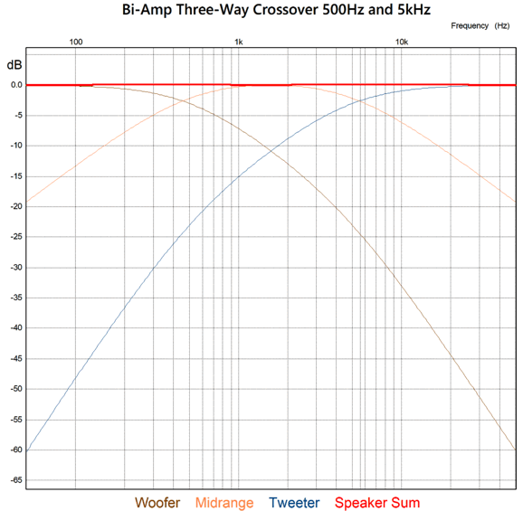
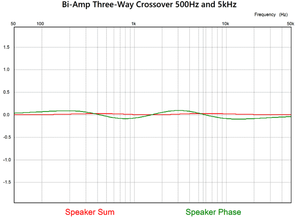
Both the frequency and phase response are flat. Here is the close-up of the two:
While less than 1 degree of phase shift and 1dB of frequency response is amazing, less than 0.5 degrees and 0.5dB is stunning. One of the real tests of flat-phase summation is the tone-burst test.
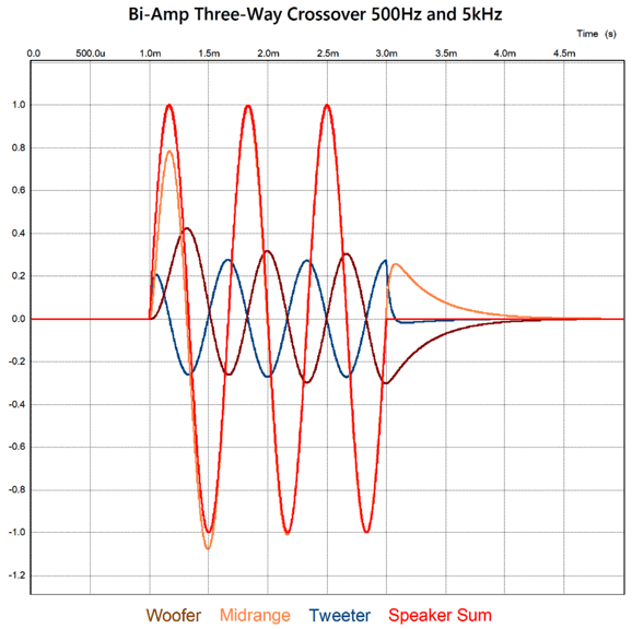
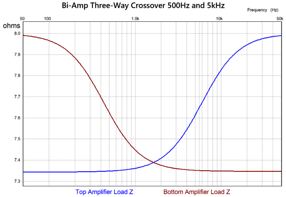
The tone-burst frequency is 1.5kHz, which is close to the geometric-mean frequency between 500Hz and 5kHz, 1580Hz. What we see is that three cycles go in and three come out. The next evaluation of the active/passive crossover's merit is that of load impedance seen by the high-frequency and low-frequency amplifiers.
Not bad. Tube-based power amplifiers will be happy. Before any reader is inclined to wonder if we are done, I must state Broskie's first rule of audio electronics: We are never done; there is always more we can do. In this design, we can eliminate one more capacitor, a big, expensive capacitor, C2.
The tweeter still sees cascading high-pass filters, while the woofer still sees cascading low-pass filters, and the midrange driver still sees the same 1st-order bandpass filter. The same frequency response plots and flat phase obtains. So why did I bother showing the previous versions? Safety. If you are not designing a powered loudspeaker system, with an internal active crossover and two power amplifiers, the previous versions with capacitor C2 are the safer path to follow. Why? I assume the midrange driver is a fast, but delicate driver. I also assume occasional mishaps occur, such as losing a ground connection on an interconnect RCA's plug connection to its RCA jack, a power failure, a massive turn thump… all of these can deliver dangerous hum or popping at full output into the midrange driver without capacitor C2. On the other hand, with the active crossover power amplifiers contained inside the loudspeaker enclosure, or at least both sharing a metal box external the loudspeaker, the hum or loud pop must still go through the active crossover, which keeps the midrange driver safe from an input signal's lost connections to ground.
By the way, the midrange driver and tweeter can be arranged instead in the 1st-order series topology, as long as both drivers share the same impedance; unlike the parallel crossover topology, the midrange driver will need a Zobel network in the series topology. Once again, the inductors will prove to be smaller in value in the parallel topology, after we subtract the midrange driver's and woofer's series inductance, Le, something we cannot do in the series arrangement, hence the need for a Zobel network. Indeed, we might not need either inductor in the parallel topology, if the crossover frequencies are carefully chosen to match driver Le, making this a two-capacitor three-way crossover.
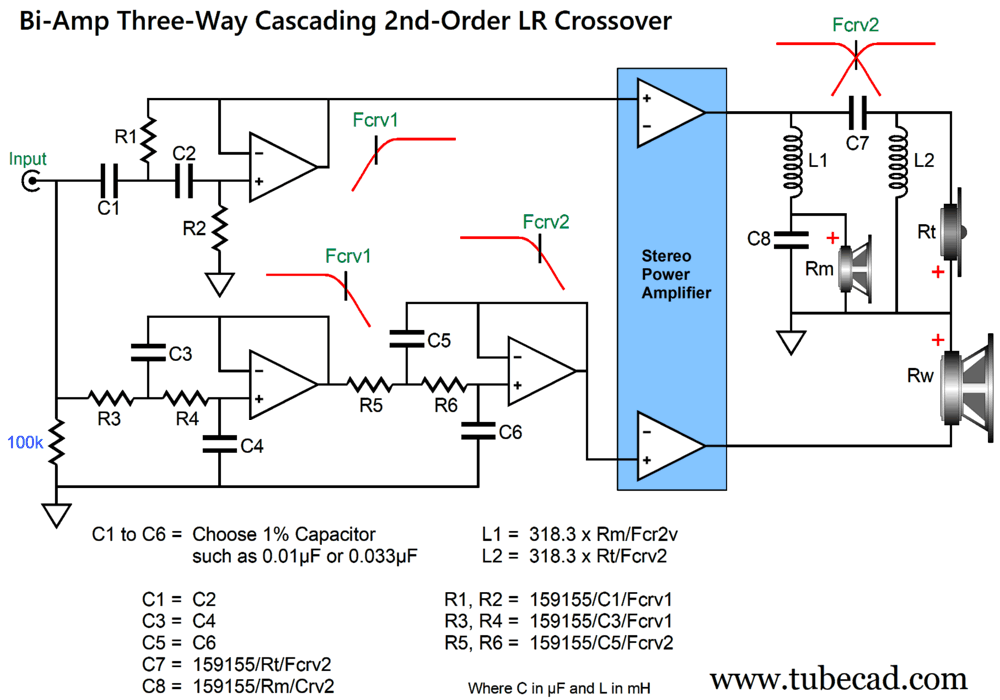
Bi-Amp 3-Way 2nd-Order Linkwitz-Riley Crossover
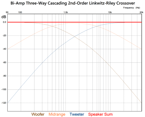
Once again, we see a mix of active and passive filters, and we get the very desirable cascade of filters, with both the woofer and tweeter seeing cascading filters. As the active low-pass filter handles all of the first crossover frequency, the woofer connects directly to the bottom low-frequency power amplifier. Note that both the woofer and tweeter are wired in anti-phase to the midrange driver. The 2nd-order Linkwitz-Riley filter alignment has the drivers down -6dB at the crossover frequency, which has greatly simplified the math required for the active filters (in contrast to the Butterworth and Bessel alignments). Here are the frequency plots for a 500Hz and 5kHz crossover.
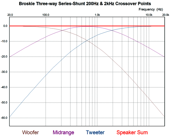
Compare this graph to the one for the 1st-order version, so you can see the far, far greater out-of-band attenuation for the woofer and tweeter. This is a disco-suitable active/passive crossover. But is it an audiophile-grade active/passive crossover? Sure, if you love disco music or play other music genres at disco-SPL levels. By the way, the Linkwitz-Riley crossover is what the overwhelming majority of high-end loudspeakers hold. Sadly, non-cascading-filters, three-way Linkwitz-Riley crossovers do not mathematically sum to flat, but then actual speaker drivers deliver nothing resembling a straight horizontal frequency plotline, so this failing is often overlooked. In fact, the crossover frequencies are often massaged to better approximate frequency-flat output. In short, passive crossovers are a pain, as the driver frequency response and impedance plots are, with the rarest exceptions, not flat. Thus the appeal of active crossover filters. In contrast, a three-way Linkwitz-Riley crossover with cascading high-pass-filters does sum to flat. It is, however, a huge hassle with passive crossovers, as the Linkwitz-Riley does not sum to a flat-impedance, thereby requiring additional impedance-flattening networks. Once again, thus the appeal of active crossover filters. Here is an example a series tweeter-cascade 2nd-order Linkwitz-Riley passive crossover.
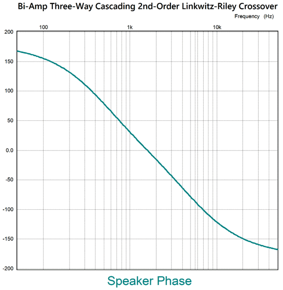
Only the tweeter gets cascading high-pass filters, but at least this crossover sums to flat. In addition, because of its series topology, it allows us to subtract the midrange driver's and woofer's series inductance (Le) from their inductors. Okay, returning to the active/passive cascading of both the highs-and-lows crossover, its phase plot, like all Linkwitz-Riley crossovers, is not flat.
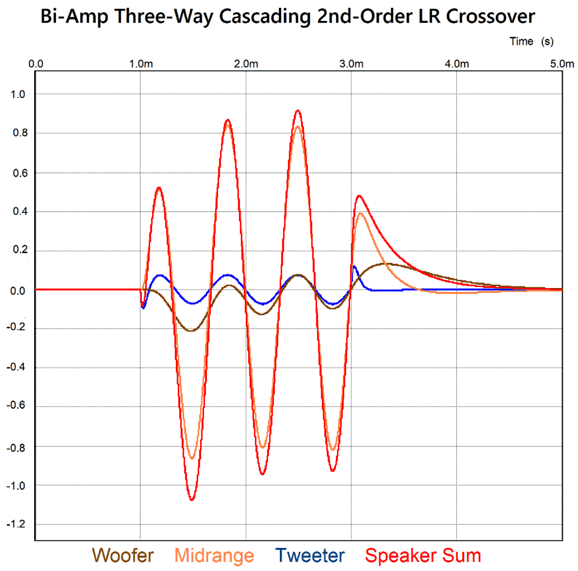
Does this matter? It does if you value transient integrity. On the other hand, if you only care about frequency response plots, it doesn't. Here is the tone-burst test of three cycles at 1.5kHz.
Not nearly as clean as the 1st-order cascading version; still, 99% of audiophiles and high-end loudspeaker makers cannot be wrong…or can they? Can 99% of people ever be wrong?
Single-Ended and Class-A-B-G
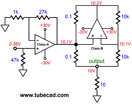
One of the Sandman class-S topologies also spurred my curiosity:
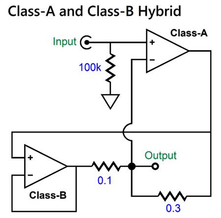
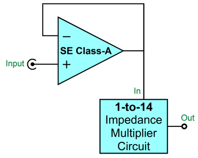
In my Post 634, I investigated the possibility of using a class-A, single-ended power buffer along with a class-B IMC (impedance-multiplier circuit) to deliver an astoundingly rare but altogether desirable harmonic structure.
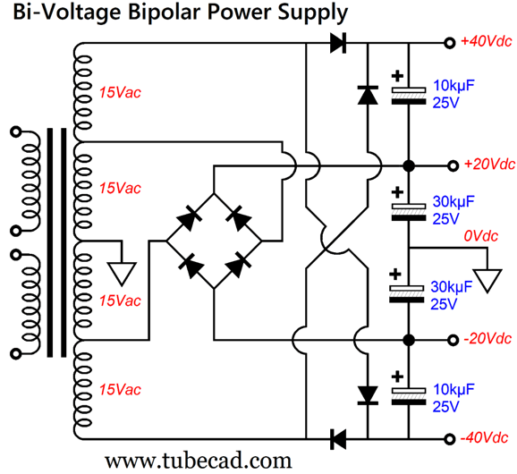
This is your assignment: read Post 634, and then return to this post. Okay, now that you are up to speed on this arrangement, we can move on to my latest idea: add class-G to the mix. Class-G uses a bi-voltage, bipolar power supply to dynamically shift the amplifier's power-supply-rail voltages as needed. In other words, at idle and when playing music at low volume, the amplifier sees a fixed relatively low-voltage bipolar-power-supply voltage. As the output increases, so too does the power-supply rail voltages. This setup saves on heat dissipation at idle, while allowing big output voltage swings, which would prove ideal when using a single-ended output stage, especially one that was constant-current-source loaded, with a theoretically maximum efficiency of 25%. Where to start? I usually end with the power supply, so let's begin with it this time. If you make power amplifiers for a living, then you just order (from a transformer company) a power transformer with multiple taps:
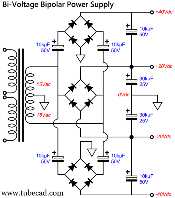
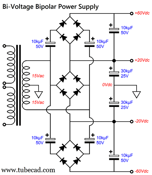
Two bridge rectifiers are used to establish the dual power-supply voltages. Note the differing capacitor values. The assumption here is that the output will only occasionally tap into the higher power-supply rail voltages, so the dissimilar capacitor voltages reflect differing rates of depletion. Of course, nothing stops us from using the same amount of capacitance for all four capacitors. If you make power amplifiers as a hobby, however, the multiple-tap power transformer is a huge hassle, if not a huge expense. The workaround is the following, which uses an off-the-shelf power transformer with a center-tapped secondary.
This requires an additional bridge rectifier and four more capacitors, but yields the same power-supply voltages. If we wish to get an even higher auxiliary bipolar power-supply voltage, we can change the top and bottom bridge rectifier terminations.
Note the increased capacitor voltages along with the increased output voltages. Yes, we can readily turn 15Vac into 60Vdc. The way it works is that all four of the 10kµF/50V capacitors girdling (flanking, surrounding) the three bridge rectifiers charge up to about 40Vdc, which they then relay to the 10kµF/50V reservoir capacitors, which sit atop and below the 30kµF/25V capacitors charged up to 20Vdc. The voltages add up to about ±60Vdc. Why "about," not exactly? We have to make allowances for wall-voltage differences and rectifier and copper losses. Okay, now that we have the power supply out of the way, we must move on to the design overview.
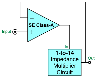
The impedance-multiplier circuit makes an 8-ohm load appears as a 112 ohms load to the single-ended amplifier (power buffer). This makes the design of the single-ended output stage so much easier, as the single-ended output stage need only draw 1/13 as much current. Notice, however, that the single-ended buffer's negative-feedback loop only extends to its output, so the single-ended stage has no control what the IMC does to the signal it receives. The workaround is to move the negative-feedback loop to the IMC's output.
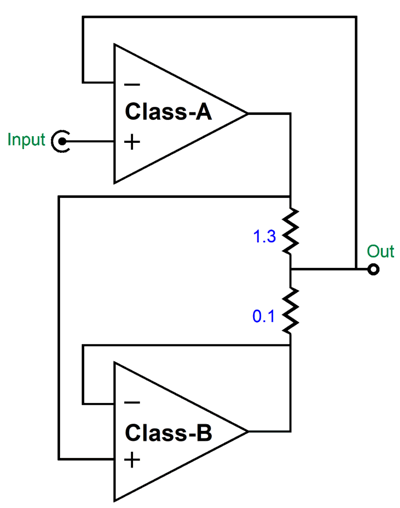
The IMC is enslaved by the single-ended stage. This is where class-B enters the picture.
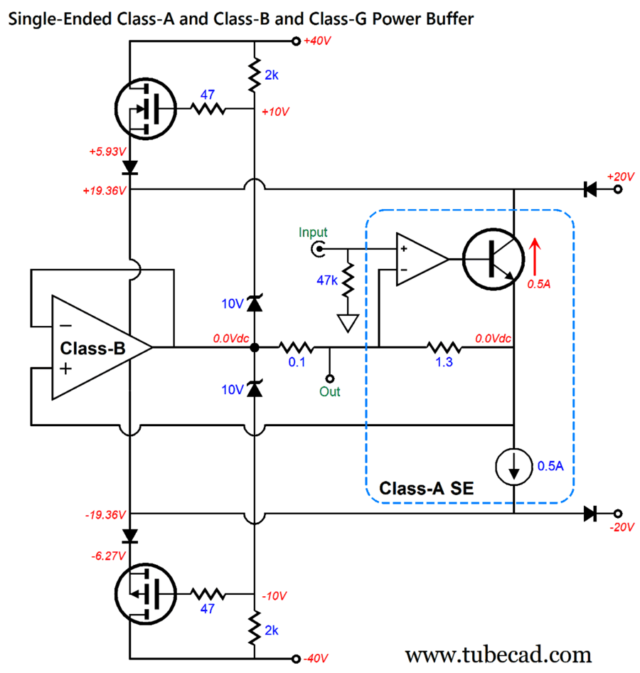
The 1.3-ohm and 0.1 resistors set the 1-to-14 impedance ratio, while the class-B amplifier runs in unity-gain mode. Next, we add the class-G element. This requires a handful of solid-state devices—four ultra-fast rectifiers and two power MOSFETs and two zener diodes—along with four resistors.
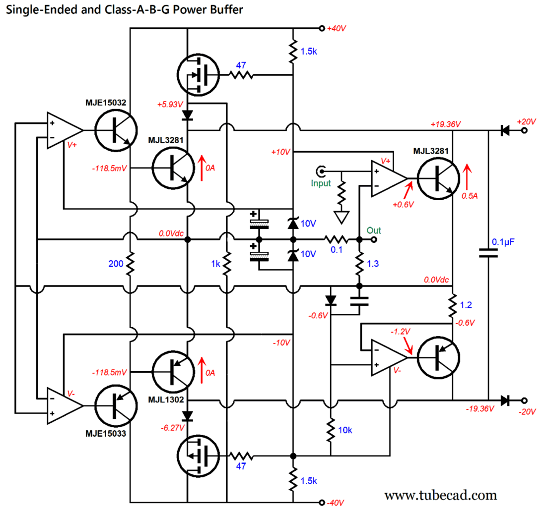
The single-ended output stage uses a single OpAmp to control the NPN power transistor, which is loaded by a 0.5A constant-current source. Both the transistor and constant-current source will dissipate 10W each. Note the absence of an emitter resistor; one isn't needed, as the 1.3-ohm IMC resistor functions as one. The class-G mojo comes from the zener diodes riding along with the output voltage swings. If the output voltage swing is large enough, the MOSFETs become engaged and pull the power-supply voltage up or down as needed. What powers the OpAmp? This is where things get sneaky: we use the two zeners as faux floating power supplies.
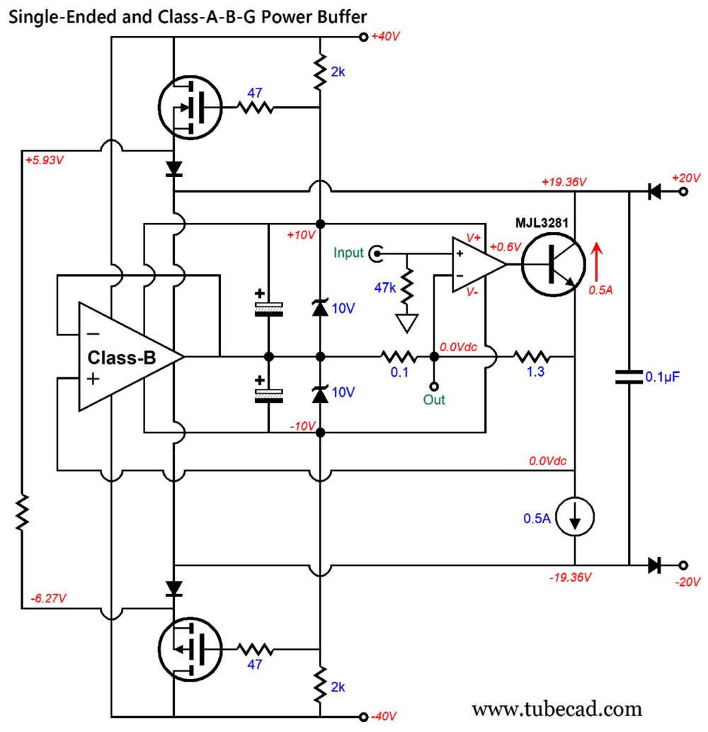
The capacitor-bypassed zeners deliver the floating ±10Vdc bipolar power supply voltage to both the single-ended output stage's OpAmp and to a portion of the class-B amplifier. In addition, the bypass capacitors allow the zeners to swing beyond the ±40Vdc bipolar power-supply voltages, which overcomes both the OpAmp's voltage-headroom limitations and allows fully turning on the MOSFETs at full output. Here is the design in greater detail:
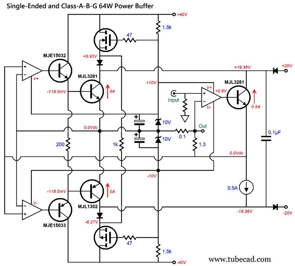
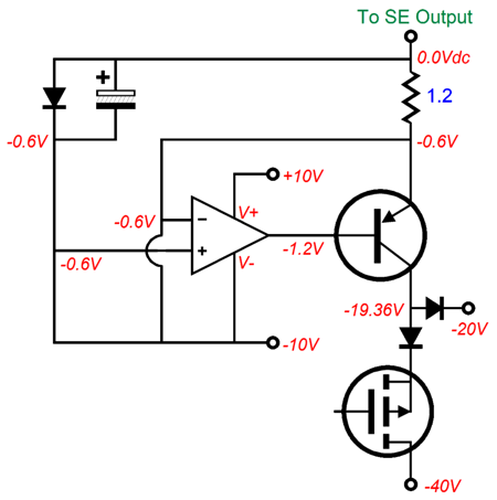
The class-B unity-gain buffer encompasses the two leftmost OpAmps and the four complementary transistors. Few OpAmps can deliver sufficient current to drive the two output transistors directly so that task is handed off to the MJE15032-MJE15033 emitter follower pair. Let's zoom in on the two OpAmps within the class-B output stage. These can be two single-amplifier ICs or a single dual-amplifier IC. The constant-current source cannot be just an LM317-HV, as its maximum voltage limit might be exceeded at full output. Instead, we can use the following constant-current source circuit.
The diode's voltage drop is used as a voltage reference, which the OpAmp uses to measure against the voltage drop across the 1.2-ohm emitter resistor. Plugging this constant-current source circuit into the design gives us this:
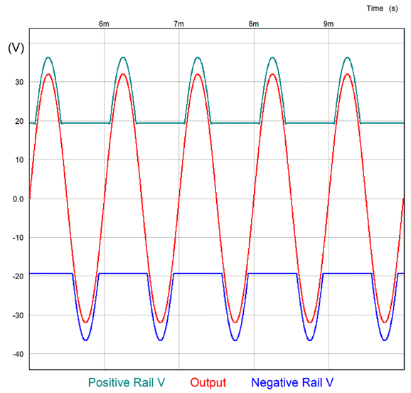
Note that the single-ended portion of the circuit can now use a dual-amplifier OpAmp—of which, there many fine contenders. The 1k resistor that bridges the two MOSFET's sources is my contribution to the art of class-G amplification. It sets a lower limit to the MOSFETs' current conduction. In other words, the MOSFETs never turn off completely, which sidestep huge switching headaches. At idle, the MOSFETs conduct only 12mA. Lowering the resistance value to 470 ohms further depressed the 3rd and 7th harmonics, but raised the 5th and 9th harmonics. My assumption is that this class-A-B-G power buffer will get its input signal from a tube-based frontend. With ±40Vdc power-supply rails, we can expect at least 32V of peak output voltage. (Why not something closer to 38Vpk? Sagging power-supply voltages under heavy use.) A peak output voltage swing of 32 volts equals 64W into an 8-ohm load and double that for a 4-ohm load. In SPICE simulations, using the SPICE Ideal OpAmp model and IRFP240 and IRFP9240 MOSFET models, the results were insanely good. Or, should I have written ASTOUNDINGLY-ATYPICALLY good.
Forget the popular notion of an ideal amplifier being straight wire with gain. What, are you mad? Every audio magazine and audiophile agrees on the straight-wire-with-gain amplifier ideal! Can 100% of people ever be wrong? Sure they can; it happens all the time. In an ideal universe, all preamps, mixers, line-stage amplifiers, tape recorders, ADCs, DACs, LPs, CDs, music streams… would be equally ideal, i.e. perfect. In such a universe, all eyeglasses would hold not corrective lenses, but perfectly flat glass, glass befitting an ideal word, where eyewear is only worn as adornment, not sight-corrective aids, as no eyes would need correcting. If you don't swallow poison, you don't need its antidote.
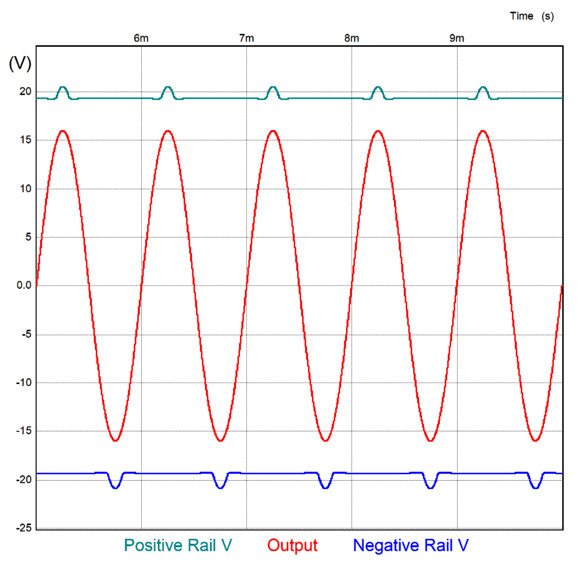
You and I don't live in that ideal universe, alas. Our recorded music comes pre-distorted, as it is already tainted with a preexisting push-pull harmonic structure, which this atypical odd-order-suppressed harmonic structure undoes. In other words, you do need to take the antidote, not a cleaner wine glass filled with poison. Proclaiming that—in a perfect universe, there would be no poison—won't save you, just as straight wire with gain won't save your ears from this:
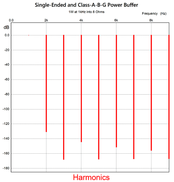
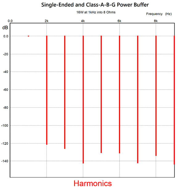
At 16Vpk of output, the class-G function just begins to operate, so this is where would expect to find some stumbling.
Here is the SPICE-generated Fourier graph:
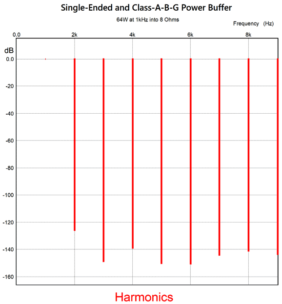
The 4th harmonic is overly suppressed, but at least we get great 7th and 9th harmonic suppression. By the way, to be -120dB down equals 0.0001% distortion. At full output, 32Vpk and 64W, we get full class-G action.
The Fourier graph show excellent performance.
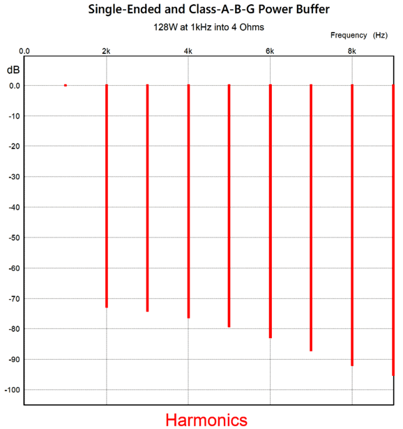
The 3rd and 5th harmonics are nicely suppressed. Of course, real OpAmps are not the same as the SPICE ideal OpAmp, but they are directionally the same. I always assume a 20dB upward shift (a tenfold worsening), which would still be excellent. What about 4-ohm loads? If we do the math, which we should always do, we see that the single-ended output stage's 0.5A constant-current source's idle current is insufficient. Here is the math: Iccs = Ipk/(IMC's ratio – 1) With a peak output voltage swing of 32V, we need 8A of peak current flow with a 4-ohm load. Thus, Iccs = 8/(14 – 1) = 0.6154A. If we run the math backwards, we find that a constant-current source current flow of 0.5A works down to a load impedance of 6.5 ohms. Of course, the obvious workaround is to increase the constant-current source's current to something like 0.7A. The problem with this increase is that the constant-current source and NPN transistor heat dissipation rises to 14W each and the extra current flow from the transistor's OpAmp. Alternatively, we could alter the IMC ratio to 17. How did I get that number? I just solved for IMC Ratio. Ratio = Ipk/Iccs + 1 With 8A of peak current flow with a 4-ohm load and a 0.5A constant-current source, we get Ratio = 8/0.5 + 1 = 17. To achieve this ratio, we replace the 1.3-ohm resistor with a 1.6-ohm resistor. Or, we could just live with reduced power output 84.5W with 4-ohm loads. How did I come up with that number? I solved for Ipk. Ipk = (Ratio – 1) x Iccs This gives us a peak output current swing of 6.5A, which squared and then divided by half the load impedance, gives us the maximum output power. By the way, the design will still cleanly put out 128W into a 4-ohm load, but just without the astoundingly-atypical harmonic structure, as the single-ended output stage's OpAmp still controls the class-B output stage's output.
Beyond the atypical-odd-order-suppressed harmonic structure, what I like about this design is that it sidesteps so many potential problems, such as too much heat dissipation, a need for floating power supplies, and class-G switching issues. As far as the four OpAmps are concerned, the power buffer's output signal is always close to ground potential, i.e. near the center of their floating power-supply voltages, due to the faux floating power supply created by the bypassed zener diodes tracking the output voltage swings, which sidesteps any OpAmp maximum input and output voltage limitations. Dang sneaky, I think. If nothing else, I find the schematic quite attractive, almost hang-on-a-wall worthy. I give the design a one-third Musk prize, leaving it to the reader to imagine the image.
Music Recommendation:Patti Smith's twelve A few months ago, a feeling of nostalgia swept over me, and I searched for Patti at Amazon Music streaming service. I discovered a 24-bit, 96kHz version of Horses and a special 50-year anniversary issue of Horses, also in high-res. A few days ago, I heard Patti again, but this time it was a track from her 2007 album, twelve, a collection 13 (yes, 13) covers of mostly 1960s and 1970's rock hits. Her signature musical style and voice remains amazingly intact half a century later. (I am going to have to hunt her other albums now.) Twelve is lots of fun, so do yourself a favor and give it a listen. //JRB
Did you enjoy my post? Do you want to see me make it to post 1,000? If so, think about supporting me at Patreon.
AI Summary Reasoning and ApproachTo summarize the key points of the document, I focused on extracting the main technical concepts, design philosophies, and practical recommendations discussed. The document covers advanced loudspeaker crossover design (bi-amp and three-way systems), amplifier topologies, and practical considerations for high-fidelity audio setups. I have organized the summary into thematic sections for clarity and included examples where relevant. Key Points Summary1. Bi-Amp and Three-Way Loudspeaker Systems
2. Active/Passive Crossover Design
3. Crossover Topologies and Performance
4. Amplifier Topologies: Single-Ended, Class-A, Class-B, and Class-G
5. Philosophy and Practical Advice
6. Music Recommendation
In summary: The document provides a deep dive into advanced loudspeaker crossover and amplifier design, offering practical schematics, mathematical guidance, and philosophical insights for audiophiles and DIY audio engineers. It balances technical rigor with real-world considerations, aiming for both sonic excellence and system reliability.
|
I know that some readers wish to avoid Patreon, so here is a PayPal button instead. Thanks. John Broskie
John Gives
Special Thanks to the Special 89 To all my patrons, all 89 of them, thank you all again. I want to especially thank
I am truly stunned and appreciative of their support. In addition I want to thank the following patrons:
All of your support makes a big difference. I would love to arrive at the point where creating my posts was my top priority of the day, not something that I have to steal time from other obligations to do. The more support I get, the higher up these posts move up in deserving attention.
If you have been reading my posts, you know that my lifetime goal is reaching post number one thousand. I have 356 more to go. My second goal was to gather 1,000 patrons. Well, that no longer seems possible to me, so I will shoot for a mighty 100 instead. Thus, I have just 11 patrons to go. Help me get there. Thanks.
New URL of the GlassWare website |
||||








| www.tubecad.com Copyright © 1999-2026 GlassWare All Rights Reserved |