| John Broskie's Guide to Tube Circuit Analysis & Design |
| August 24 2026 | Post Number 645 |
||||||||||||||||||||||||||||||||||||||||||||
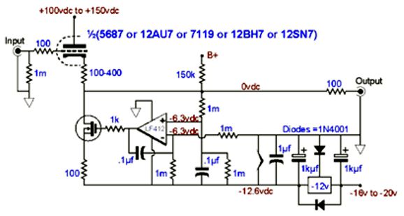
The Return of No Gain In days past, a ready reserve of gain proved a feature, as it could overcome the large span of phono cartridge outputs and various signal sources, such as FM tuners, tape decks... At the most, I can see a need for a fourfold amplification (12dB) in some systems, as some tube-based power amplifiers require over 2Vpk to 3Vpk of input signal to be driven to full output. Well, if you don't need any gain, should you consider a passive line stage that only holds an input-signal selector switch and a volume control, but no active electronics? Perhaps your confidence the famous FACT that less is more in audio electronics, compels you to contemplate the theoretical advantage of eliminating all those electronic parts and their power supplies, and to imagine the sweet, short path the signal travels to get to the power amplifier. Alas, I cannot join you on this reverie, as I have built many passive line stages, some holding the most expensive volume controls, switches, resistors, and wire. All proved unsatisfying in the end, as the resulting sound always seemed unanchored and insubstantial, merely a wraith or shadow of its substantial self. The theory that less must be best gave way to hard experience. My system didn't need signal voltage gain just current gain. Back in the early 1990s, I designed and built my first No-Gain, No-Pain tube-based buffer. As I was still under the sway of the theoretical advantage of passive line stages, I had designed the circuit just because it was novel and interesting. In 1998, I detailed the design at my GlassWare website, in a section titled "Circuit of the Month," which was a precursor to the Tube CAD Journal. The design used a simple cathode follower loaded by a compliant-constant-current source controlled by a DC servo that eliminated both any DC offset and the need for an output coupling capacitor. Forgive the following GIF schematic from 1998:
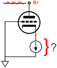
The triode's idle current is set by its cathode resistor, just as if the resistor terminated into ground. The compliant-constant-current source below it then matches the triode's current flow and prevents a DC offset voltage. The 150k resistor to the B+ voltage simply provides a current path to the B+ voltage when the tube is either missing from its socket or still cold and not conducting. The negative 12V voltage regulator, along with the diode in series with its ground pin and ground, establishes the -12.6Vdc negative power-supply rail. The LF412 OpAmp with an FET input stage cannot accept input signal greater than its positive power-supply voltage, i.e. 0V in this case, so the four 1M resistors are used to split the -12.6 voltage, thereby delivering safe DC voltages to the OpAmp's inputs. The tube's heater element was also powered by the negative power-supply rail. You can read more about the circuit in my Post 102, where I explain the importance of tightly-matched 1M resistors in the design. (When I built my No-Gain buffer, I lived in Silicon Valley and had easy access to inexpensive 0.01% resistors at electronic-surplus stores.) In addition, you will see a nicer schematic:
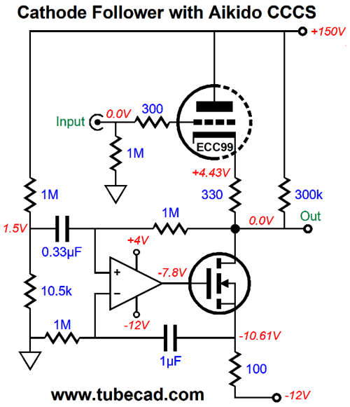
Six years ago, I revisited the No-Gain, No-Pain buffer stage in my Post 520. I had decided to add some Aikido Mojo to the design:
Dang sneaky ("sneaky is my egalitarian—indeed, equalitarian—euphuism for "clever," which in contrast is inegalitarian and immodest in the extreme). Does a cathode follower really need Aikido-Mojo enhancement?
It really does, as a current-source loaded cathode follower exhibits a PSRR only equal to 20Log(1/mu), where mu is the triode's amplification factor. A 6SN7 offers a mu of 20, making for a PSRR of only -26dB. By the way, the hidden assumption behind the circuit is that negative 12V power-supply rail is well regulated, so much so that in AC terms it is virtually identical a connection to ground. This bothered me a tad. But it was the need for the two capacitors within the DC servo circuit that bothered me more, as the two complicate the circuit design. Thus, my quest was to eliminate one capacitor and still inject Aikido Mojo.
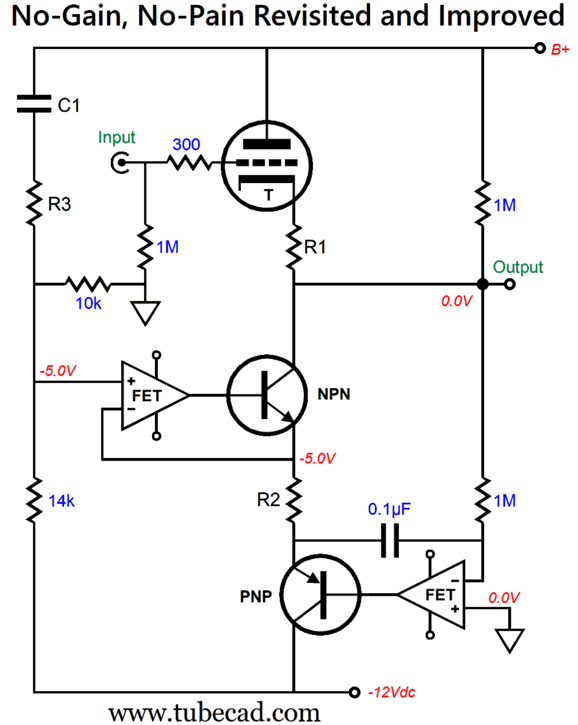
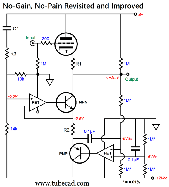
No-Gain, No-Pain Revisited and Improved
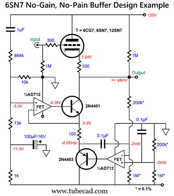
Two OpAmps are used. The one on the left handles the Aikido Mojo, while the one on the right functions as a DC servo. The two transistors are low-noise, low-voltage and low-wattage types. As long as the cathode resistor's voltage drop is not too great, say more than 5V, resistors R1 and R2 can match each other in value. Capacitor C1 and resistor R3 set the amount of power-supply noise to inject to create a power-supply noise null at the output. No output coupling capacitor is needed, but one could be used, such as a PIO type, to add sonic flavoring. In fact, two outputs can be offered, one capacitor-coupled for solid-state power amplifiers and one DC coupled for tube-based amplifiers. The two OpAmps can be housed in an 8-pin dual-amplifier IC package. If the OpAmp cannot tolerate input voltage near or greater than the V+ voltage, they will require a low voltage bipolar power supply. My original workaround was to use four super high-tolerance 1M resistors. Here is an example:
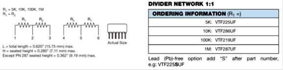
Where do you get 0.01% resistors? One good source is the Vishay Dale thin-film conformal, single in-line, through-hole resistor network (about $10 each):
The worst-case scenario of the 1M resistors being either 1.0001 or 0.9999 off the 1 meg-ohm nominal value results in a potential DC offset voltage of no more than ± 2.13mV, assuming the OpAmp does not bring its own DC offset. If we used 0.1% 1M resistors, the potential DC offset voltage rises to ± 21.3mV. Of course, if you are driving a tube-based power amplifier or a solid-state power amplifier that does not amplify DC voltages (which is the vast majority of them, as DC amplifiers were a 1990's fad), then you need not overly worry.
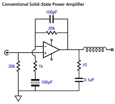
Note that the 100µF non-polarized electrolytic capacitor prevents the amplifier from amplifying any DC offset at its input, as the amplifier ceases being an amplifier at DC and becomes a unity-gain buffer. If we pull back, we will see that the two-resistor voltage dividers need not exactly split the negative power-supply rail voltage, just lower the center voltage below the ground potential enough not to cause the OpAmp to latch up. For example, I recall the very long-in-the-tooth input-FET AD712's maximum positive input voltage being 2V less than its V+, which in this example would be 0Vdc, so -2Vdc is a suitable target voltage.
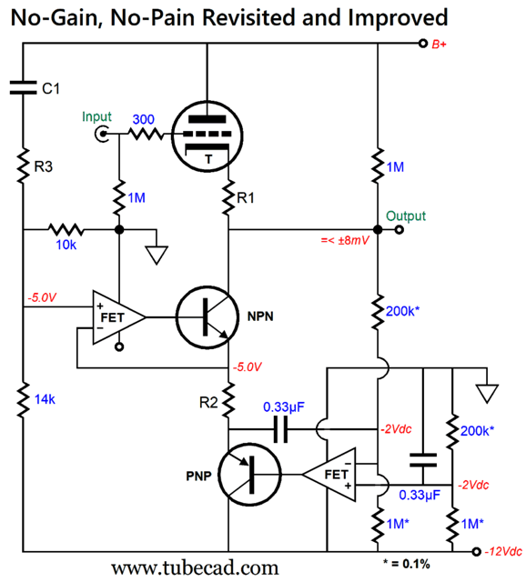
Note the increased capacitor values within the DC servo circuit due to the 200k resistors. With 0.1% resistors in the DC servo circuit, the worst-case DC offset is only ±8.16mV. With 0.01% resistors, the worst-case DC offset falls to 1mV. Here is a design example with a 6SN7 (or 6CG7 or 12SN7 or 12SX7).
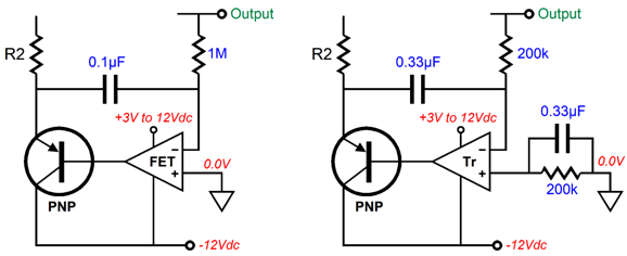
By the way, some (but not all) OpAmps with transistor input stages can readily accept an input voltage equal to their positive power-supply voltage. The problem with these OpAmps is that the transistor-based input stage draws current at its inputs, not much, but enough to create a big DC offset voltage with high-ohmage resistor values.
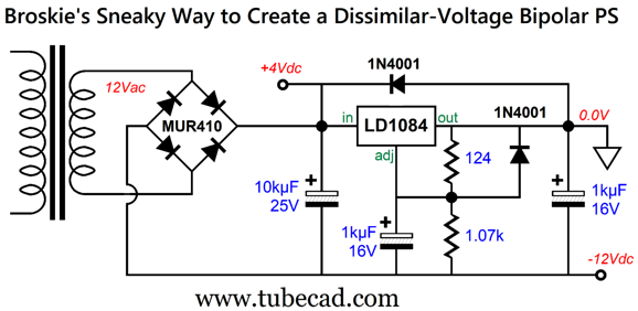
Note that a bipolar power supply is used in both examples. One the left, we see that the FET-based input stage can simply ground the non-inverting input, whereas the transistor-based input stage requires the additional 200k resistor and capacitor. With the additional resistor and capacitor, both of the OpAmp's inputs see the same current-induced offset voltage, so they cancel. Nice. Here is how we create a dissimilar-voltage bipolar power supply:
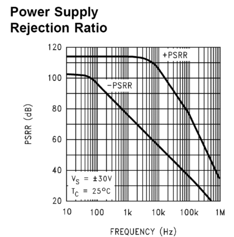
The -12Vdc voltage is regulated, while the +4Vdc voltage is not; indeed, it is relatively dirty. Does this matter? Not really, as most OpAmps exhibit far better PSRR figures on their +V pins compared to their –V pins.
If you are still nervous, the +4V output voltage can be cleaned up with a 10-ohm RC resistor and 1kµF capacitor. Okay, how do you figure out the needed part values? Of course, you can use SPICE and machine gun your way to the optimal values—or you can use the following table.
The 6J5, 12SN7, and 12SX7 share the same values as the 6SN7. Of course, a triode-connected pentode, such as the EL84 or EL86 could be used, as well as DHT tubes, such as the 2A3 or 300B, but it will be up to you to establish the optimal values. One trick when dealing with reality and seeking the best Aikido Mojo is to use a specially dirtied high-voltage power supply. Let's say that the B+ voltage power supply holds a 100µF reservoir capacitor bypassed by a 3.6µF film capacitor. We disconnect the 100µF capacitor connection to the output voltage, thereby relying on the 3.6µF capacitor to do the heavy filtering, which it can't, thereby creating an especially noisy B+ voltage, which makes for obvious PSRR-improvement adjustments. Think of it as an audio magnifying glass.
Augmented Cathode Follower
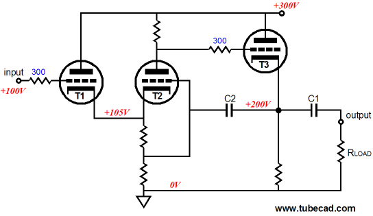
Triode T1 drives triode T2's cathode making T2 function as a grounded-grid amplifier, so there is no phase inversion at the output. Internal coupling capacitor C2 relays 100% of the output signal to T2's grid, creating a negative-feedback loop, so unity-gain results, along with lower distortion and output impedance. The hassle with this circuit is that triode T3's cathode is situated +100V above T1 and T2 cathodes, so the heater power supply must be referenced to +150Vdc, so as to split the voltage difference. In addition, capacitor C2 must be relatively large in capacitance. Another example comes from my Post 212:
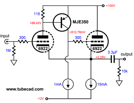
This hybrid augmented buffer requires a negative power-supply rail and delivers such amazing performance in SPICE simulations that I dared not post the results, as no one would believe them. This is definitely not your grandfather's cathode follower. I rather cheekily labeled this topology the Brains and Brawn Cathode Follower.
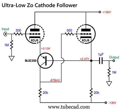
Last year's Post 616 showed another hybrid augmented cathode follower, which I named the Ultra-Low Zo cathode follower.
It uses the bastode configuration and uses resistors rather than constant-current sources, although they could be used, as in the following design example:
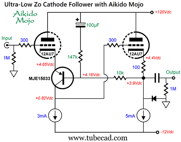
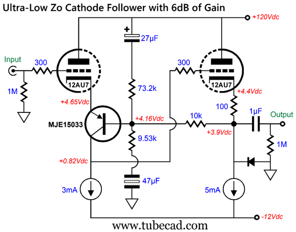
This variation employs Aikido Mojo to enhance its PSRR, which got me thinking about how to add some output gain to the circuit; not a lot of gain, say just 2X or +6dB.
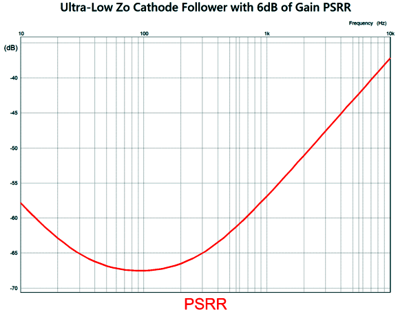
Note the use of plain electrolytic and non-polar electrolytic capacitors. Why not just non-polar electrolytic capacitors? They typically stop at a maximum voltage of 100V. Also note that the 9.53k negative feedback resistor sets the gain of +6dB. The protective diode limits the maximum negative output voltage to about -4.5Vpk. An additional safety diode can be added to the input triode by bridging ground to its cathode with the diode. The PSRR is exemplary:
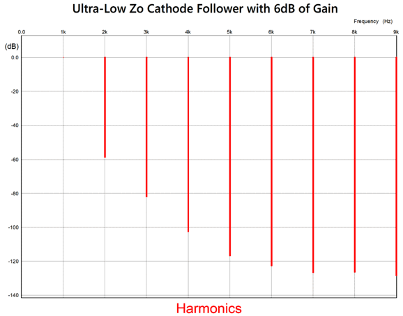
With 1Vpk of input signal at 1kHz and 2Vpk of output signal, the SPICE-generated Fourier graph reveals a lovely single-ended cascade of harmonics.
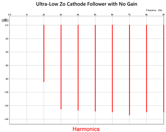
With no gain, the Fourier graphs shows a strong 2nd harmonic with the higher harmonics greatly suppressed.
By the way, to be down 80dB equals 0.01% distortion.
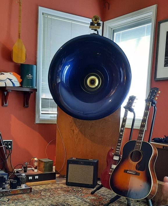
Sonic Miracles A previous improvement was wrought by digitally time-delaying the subwoofer's input signal to bring it into time alignment with the midrange horns, as the subwoofers are nearer to the listener. This had the effect of moving the deep bass from being free-floating to being anchored in the instruments that produced the bass.
Sadly, the Klipsch corner-horns rattled the Lowther fullrange drivers, occasionally resulting in their sympathetic resonance. Steve's first thought was to separate the Lowther fullrange drivers from the Klipsch corner-horns with some Resonix sheets between the two, and it worked, no buzzing. Steve then told me that he had a bunch of marble left over from some home improvement work. I told him to avoid it, as marble rings like a bell; instead, he should get some gray cast iron, as that is what is used in machine shops to prevent vibrations. He wasn't sure about trusting me about the marble (or the iron), so he called other audio luminaries; they said: marble rings like a bell. He then asked Gemini AI (he pays for the fancy version) about gray cast iron. It said:
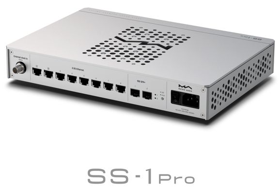
So, Steve ordered some thick gray iron sheets from out of state, cut to conform to the Khorn's top profile, along with some synthetic marble and six used Stillpoints isolation footers; he already had some of them under each Khorn. When I found out how expensive the gray cat iron was, and that just the shipping of the gray cast-iron slabs cost $200, I began to worry that it would not pay off. I was so wrong. The cast iron and synthetic marble and Resonix and Stillpoints have utterly transformed his system. (It turned out that he had his StillPoint footers upside-down on the Khorns, which have been up righted.) Every goddamned thing improved, the subwoofers, the Khorns, the Lowther horns. The bass is taut and coherent now. It's insane how much tighter everything sounds now. His system went from grade B+ to grade A. Our shared friend, Glenn, and I listened in disbelief, as we had both written off the Khorns as the weak sonic link. Sadly, our also shared friend, Ken, left to return to California just the day before the sonic transformation. Second sonic miracle: When Steve told me that he had just bought a $1500 network switch, I was glad that I didn't have the money to do such crazy impulse buys. It goes between the CAT-6 wall connector and his streamer.
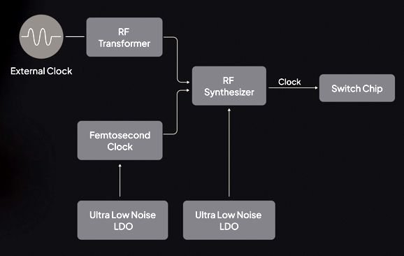
Glenn and I were leaving Steve's place, when the Matrix SS-1 Pro switch arrived, and Steve insisted that we stay to hear it. We had spent the morning running test tones and reading SPL meters in an attempt to figure out why his tweeter, which claims to go out to 30kHz, falls like a brick past 15kHz. No music, in other words. Measuring is hard work. Hell, serious listening is also hard work. Okay, I was impressed by the SS-1 Pro's build. Solid, heavy, beautiful to behold. Steve first played four tracks that Glenn and I know by heart, without the Matrix, streaming from Qobuz. Sounded flat, boring, a bit dull. (At least twice, I have subscribed to Qobuz, as I quite like its clean layout and capsule reviews and biographies—but I could not stand the constantly recurring micro dropouts, which have only occurred twice with Amazon Music streaming service in the last 6 years or so and about twice a year with Presto streaming service.) With the Matrix in place, we listened to the same tracks. Instantly, and I mean in the first 3 seconds, we heard a truly huge improvement. Increased dynamics, better imaging, and seemingly louder playback. Wow! Check out this review. The Matrix connects through optical cable, which galvanically isolates the data stream from the signal source ground. (This might be a large part of the secret sauce, as I have wanted to hear Steve's system with the network cable disconnected from his system for a long time now.) It also includes a fancy femtosecond clock and the best and latest and finest electronic goodies.
In other words, further digital domestication. In fact, the stream from Qobuz sounded better than the SSD in streamer, a sonic first, as the SSD had always sounded better than any stream. With digital, unlike much of analog, newer is always way better. In short, $$$ well spent. If nothing else, the Matrix is super well-made and heavy and attractive. Steve's system has advanced to grade A. Hell, Steve's system now deserves an A+.
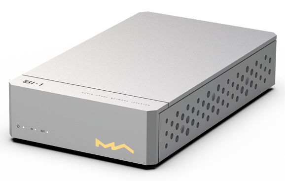
Matrix Audio also makes a simpler and cheaper SI-1 Audio Grade Network Isolator, which might deliver much of the same sonic goods at a far lower price, for those who do not need multiple network outputs.
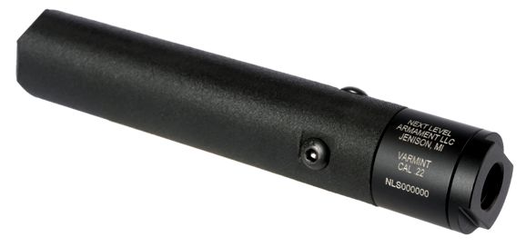
Semi-Disposable Suppressor
From their website:
Okay, this is brilliant, and I hope they make millions. Needless to say, I want one. https://www.youtube.com/watch?v=5EpASitmjsY
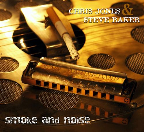
Music Recommendation: //JRB
Adobe AI Summary: Reasoning and ApproachTo summarize the key points of the document, I focused on extracting the main technical arguments, design insights, and practical recommendations presented. The document covers both technical aspects of audio electronics (specifically zero-gain tube buffer circuits and passive line stages) and practical audio system improvements, as well as some related product recommendations and anecdotes. Below is a structured summary of the key points, with examples and explanations for clarity. Key Points Summary1. The Case Against Excessive Gain in Modern Audio Systems
2. Zero-Gain Tube Buffer (No-Gain, No-Pain) Designs
3. Augmented Cathode Follower Circuits
4. Practical Audio System Improvements
5. Product Highlight: Semi-Disposable Suppressor
6. Music Recommendation
Example Implementation
This summary captures the technical, practical, and anecdotal highlights of the document, providing actionable insights for audiophiles and audio engineers.
Did you enjoy my post? Do you want to see me make it to post 1,000? If so, think about supporting me at Patreon.
|
I know that some readers wish to avoid Patreon, so here is a PayPal button instead. Thanks. John Broskie
John Gives
Special Thanks to the Special 89 To all my patrons, all 89 of them, thank you all again. I want to especially thank
I am truly stunned and appreciative of their support. In addition I want to thank the following patrons:
All of your support makes a big difference. I would love to arrive at the point where creating my posts was my top priority of the day, not something that I have to steal time from other obligations to do. The more support I get, the higher up these posts move up in deserving attention.
If you have been reading my posts, you know that my lifetime goal is reaching post number one thousand. I have 355 more to go. My second goal was to gather 1,000 patrons. Well, that no longer seems possible to me, so I will shoot for a mighty 100 instead. Thus, I have just 11 patrons to go. Help me get there. Thanks.
New URL of the GlassWare website |
||||||||||||||||||||||||||||||||||||||||||||

.png)







| www.tubecad.com Copyright © 1999-2026 GlassWare All Rights Reserved |