| John Broskie's Guide to Tube Circuit Analysis & Design |
| September 06 2026 | Post Number 646 |
||||
Extending the Bandwidth
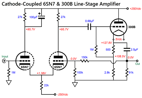
Here is his original design:
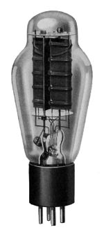
First of all, the 6SN7-based cathode-coupled amplifier easily develops the desired 6dB of gain (1:2) he sought. Situated in a fancy enclosure, this existing circuit could sell for and easy $5k, the 300B bestowing an expensive glow. In my SPICE simulations, the amplifier's high-frequency bandwidth hit its -3dB frequency at around 250 kHz, which many, including me, would deem adequate. If you want higher bandwidth, the best way to extend the high-frequency cutoff requires altering the negative-feedback loop resistor values, as the 150K and 100k resistances in parallel create an output impedance of 60k that forms a high-pass filter with the right 6SN7 triode's grid-to-plate capacitance. Thus, the lower negative feedback resistor values result in a higher cutoff frequency. Since the output coupling capacitor will now have to drive a lower load resistance, the output capacitor must also be increased in value to preserve the low-frequency bandwidth. Yes, everything in electronics is a tradeoff. So are we done? No. Let's examine the circuit. Note that the 91k resistor is superfluous, as the negative-feedback-loop voltage divider resistors already define a path to ground for the output coupling capacitor. In other words, it should go. Next note what is missing: grid-stopper resistors. While I often omit them from SPICE circuits, these are not optional in reality, especially on the cathode follower.
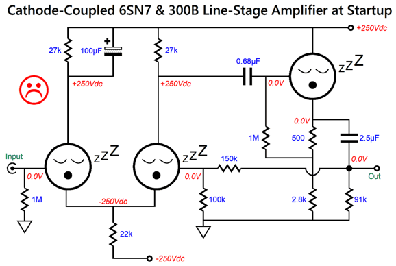
Okay, we agree to add grid-stopper resistors. Next, let's examine what happens at startup, when the tubes are cold and not conducting.
The 6SN7 grids see ground potential (i.e. 0V), while the plates see +250Vdc and the cathodes see -250Vdc. Not good, as we risk cathode stripping, wherein the 500V voltage differential and the tiny distance between cathode and plate create an electrostatic attraction so great that portions of the cathode's surface rip away and fly off and crash into the plate. The workaround is to add safety diodes (1N4007). Next, we examine if the internal 0.68µF coupling capacitor is needed. As it stands, the 300B's grid sees +108.5Vdc at idle, while the two 6SN7 plates sit at +95.7Vdc, not that big a difference. In other words, do we actually need the internal coupling capacitor? Nope.
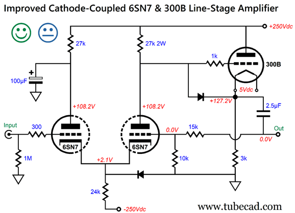
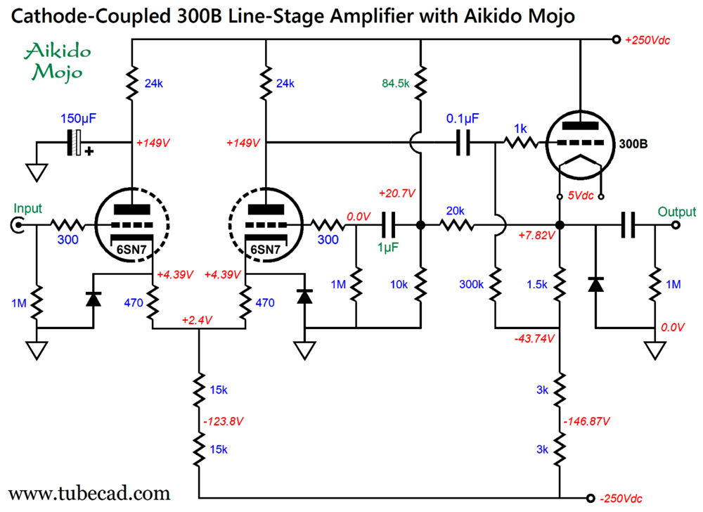
Note that the 100µF decoupling capacitor now terminates into ground, not the B+ voltage. Also note the altered resistor values throughout. Now, at startup, the 6SN7 grids still see 0V, but the cathodes see only -0.7Vdc. Thus the happy face. Why the uncommitted face? The PSRR in SPICE simulations was poor. In addition, the 2.5µF output coupling capacitor is dragged down by the 25k negative-feedback loop resistance. In other words, we have to use a large-valued capacitor, which given the cost of Audio Note, Audyn, Dueland, Jupiter, Mundorf… coupling capacitors, it behooves us to optimize the circuit to allow a lower-valued output capacitor. Then there is the issue of the 3k cathode follower load resistor, which is far too low in resistance to roughly approximate a constant-current source. My deluxe remake:
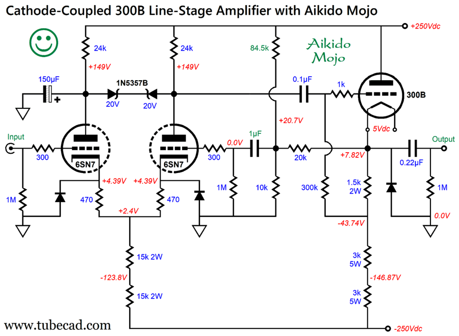
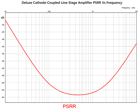
The two zener diodes allow both of the 6SN7 triodes to partake in the slow 10-second charging of the 150µF capacitor. In addition, my version vastly improves the PSRR. John, why do you obsess so much over PSRR? With a good power supply, it simply does not matter. Really? Well, I am reminded of when Enzo Ferrari famously stated, "Aerodynamics are for people who cannot build engines." When lower-horsepower racecars started beating his more powerful racecars, however, Enzo changed his tune. I always thought that an analogous sentence would be, Accuracy is only for rifles that shoot wimpy bullets. If a tube-loving audiophile hopes to beat solid-state gear, he cannot get away with the typical tube-gear's poor PSRR, for inky-black silence is a highly desirable goal in serious listening. Here is the SPICE-generated PSRR graph:
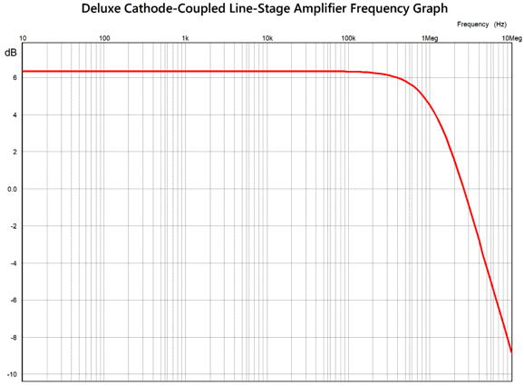
The frequency response extends out past 1MHz.
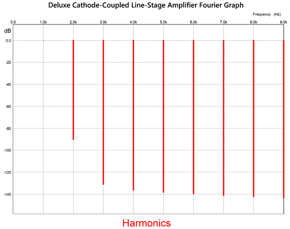
The distortion is plenty low:
So, are we done? Not a chance. I don't much like the 0.1µF internal coupling capacitor. Here is a workaround:
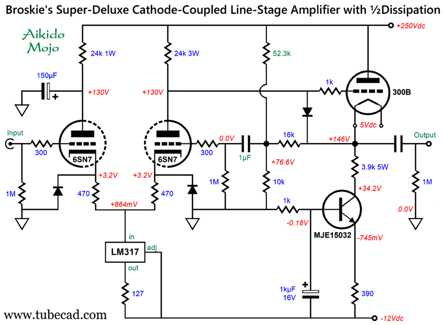
Not only have we eliminated the internal coupling capacitor, we have also halved the 300B's dissipation and increased the cathode-follower's cathode load resistance. The safety diodes do their job. The Aikido Mojo rejects the power-supply noise. Situated in a fancy enclosure, this modified circuit could sell for and easy $7.5k, the enhanced performance justifying the price increase. Would I ever actually build such a line-stage amplifier for my own use? No. Why not? Beyond the huge cost of high-quality 300B tubes, the total heat dissipation for a stereo unit is 43W, not including heater element dissipation. In other words, it would be the same as a small tube-based power amplifier. Is there no way to decrease the dissipation while retaining the sonic glory? Indeed, there is.
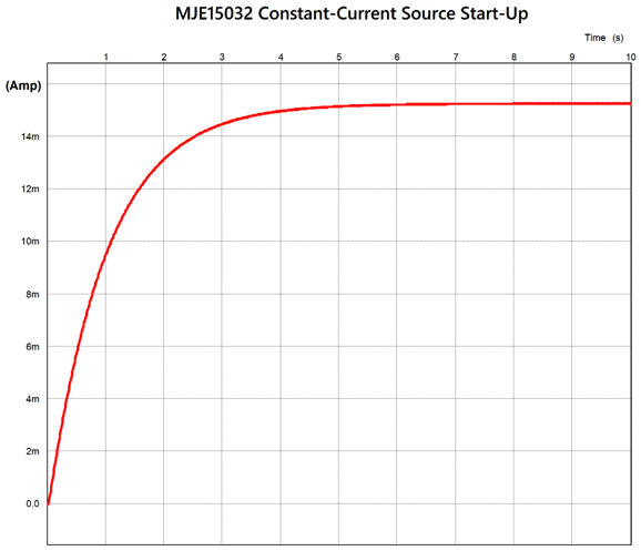
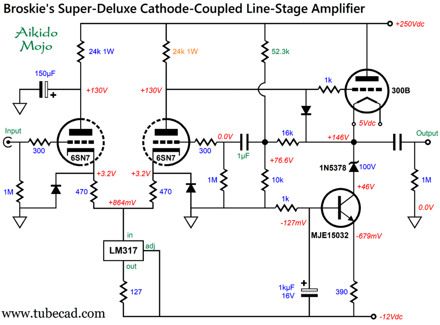
The negative power-supply rail voltage is reduced to -12Vdc, which allows us to use solid-state constant-current sources for both the cathode-coupled amplifier input stage and the cathode follower output stage. The MJE15032-based constant-current source ramps up slowly in current flow due to the 1k resistor and 1kµF capacitor, which eases the 300B turn on and extends its life. In addition, it allows for easy auto-biasing, in spite of 300B aging or different 6SN7s.
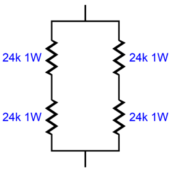
(Do not forget that the negative-feedback loop resistors are effectively cathode resistors in this circuit, as they define a DC current path from ground to the 300B cathode.) The wattage disparity between the two 24k plate resistors is due to the one on the right seeing a near 250V voltage drop at turn on. The problem here is that it is difficult to find high-quality plate resistors in a 3W rating. The workaround is to use a series-parallel arrangement of 1W resistors.
If we replace the 3.9k cathode resistor with a 5W, 100V zener, then we can use, instead, two 1W 24k plate resistors.
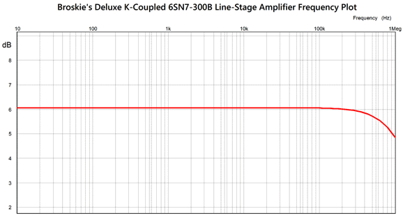
If the inclusion of the zener offends your audiophile sensibilities, you can bypass it with a high-quality film capacitor; hell, even a high-quality electrolytic capacitor could be used. Do not forget that although the zener is in the triode's current path, it terminates into a constant-current source. In other words, it would be hard for the zener to screw up the sound, even if it wanted to do so. In SPICE simulations, the distortion was so low that I won't bother showing the Fourier graph, as it was too good to be believed. On the other hand, the frequency response can be believed.
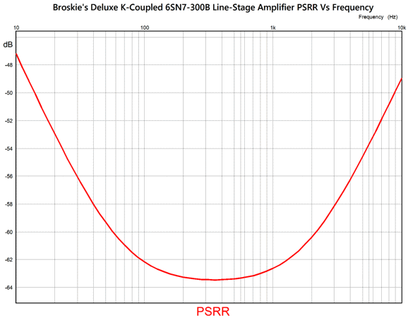
The PSRR was exemplary.
Before you ask, situated in a fancy enclosure, this variation circuit could sell for and easy $10k, which would warrant even fancier knobs and isolation feet. Before undertaking such a construction project, I would try something more practical (and far cheaper).
Broskie's Practical-Deluxe CCA Preamp
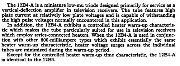
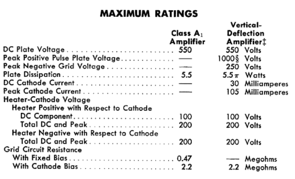
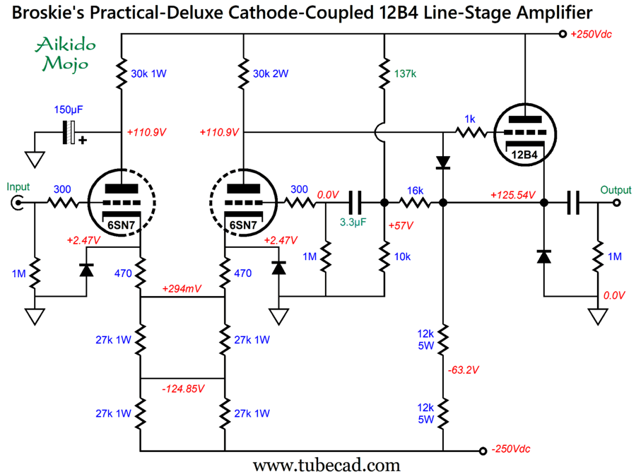
This means we can use a single 12Vdc heater power supply for two 6SN7s and two 12B4 tubes. If we want an all-tube build, the following works.
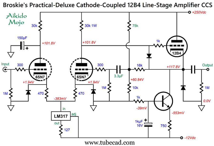
Or, if we are willing to add some solid-state devices (other than the safety diodes), the following also works.
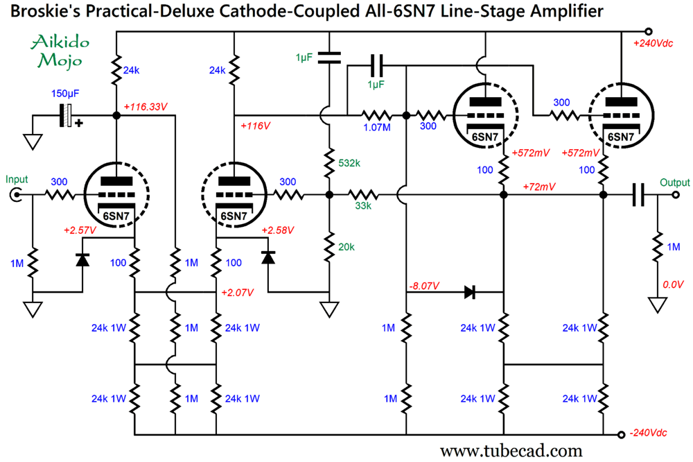
Broskie's Practical-Deluxe CCA All-6SN7 Preamp
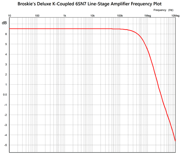
We are back to a symmetrical bipolar power supply and all-tube design. The circuit uses a DC negative-feedback loop and AC coupling capacitor to bypass the 1.07M resistor to retain more open-loop AC gain. Since all the 6SN7 cathodes are near ground potential, they can share the same heater power supply without worry. The Aikido Mojo resistor, 532k, must be capacitor coupled to the B+ voltage in this circuit. Okay, situated in a fancy enclosure, this variation on the circuit could sell for and easy $3k to $5k, depending on how thick the faceplate was and how heavy the knobs are. Yes, a thick faceplate and massive knobs can easily add $1,000 to $2,000 in price, but not sonic worth. Or, am I wrong here? The high-frequency bandwidth goes out beyond 1MHz.
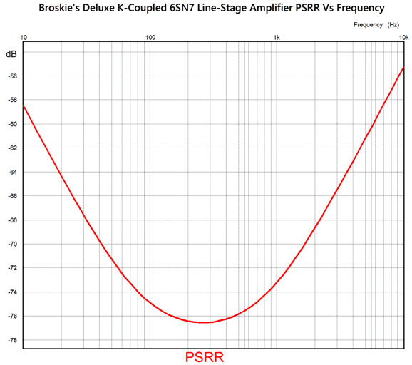
The PSRR is exceptionally fine.
Positive Vibes Preamp
The 12DW7 is a twin-triode tube with dissimilar triodes, with one being a 12AX7 type, the other a 12AU7 type. I pretty much hit the target, as the circuit delivered a peak-to-peak output of 140V with 1Vpk of input signal. The THD in SPICE simulation came in at about 1%. The output signal was not perfectly symmetrical, as it swung negatively 72V and positively 68V. Is this a problem? No, especially not in a two-stage single-ended power amplifier, as the output triode will over respond to positive input swings than to negative swings. In other words, it's easier to turn a triode on than to turn it off. Well, this positive-feedback input stage delivers a complementary inverted output signal, so the two curvatures will tend to cancel. With an input signal of 0.1Vpk, the THD falls to 0.1%, while producing a lovely single-ended cascade of harmonics. The ACF output stage provides excellent PSRR and presents a lower output impedance than the positive-feedback input stage provides, due to the positive feedback. Okay, what if we were willing to forgo the all-tube aspect and incorporate some solid-state hybridization? For example, we use a mu-follower input stage instead, while still retaining the ACF output stage.
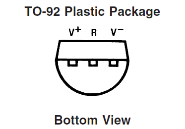
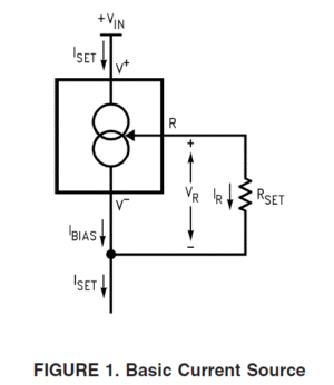
The total gain rises to almost 1:80. The constant-current source can be made from an LM334 IC.
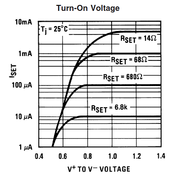
From an inspection of the graph, we see that a 68-ohm current-setting resistor is needed for 1mA of current flow. Note that with a cathode-to-grid voltage of only 0.9V, we just enter the plateau of constant-current flow. If the B+ voltage were increased to 400Vdc and a 1.5k cathode resistor were used for the bottom 12AX7 triode, the cathode-to-grid voltage climbs to a healthy 1.5V. Sadly, the two cathodes are then 200V apart, which is too great to safely split the difference by referencing the heater power supply to 100Vdc. The workaround would be to use two 12DW7 tubes, with two floating power supplies, one referenced to +50Vdc, the other to +250Vdc.
Mind you, the stock of NOS 12DW7/7247/ECC832 tubes dwindles away daily. Presently, JJ makes a nice 12DW7, but will it tomorrow? By the way, both these design examples yielded the same PSRR-versus-frequency plot in SPICE simulations, with the same capacitor and two-resistor voltage-divider part values but differing B+ voltage and 12AU7 cathode resistor values.
I won't bother showing the Fourier graph for 80Vpk of output, as it was insanely too good, which partly is an artifact of a misguided SPICE triode math model with its flawed assumption of a perfectly constant amplification factor (mu), something that my own triode math model assiduously avoids. See my Post 422 for further explication. In addition, SPICE assumes a constant-current source that reality fails to deliver.
Okay, this was a side-trip into single-ended power amplifier design, so let's return the topic of low-gain preamps that employ a tad of positive feedback. Time to downshift. Positive feedback, in contrast with negative feedback, increases gain, distortion, and output impedance. So why introduce it? It can, in extreme moderation, instill a certain vibrancy and vivacity to the sonic signature. Too much positive feedback, however, results in wild howling and screeching. Never forget, moderation in everything (including moderation). Here is a modest effort at positive feedback.
It delivers a gain of 1:10 (20dB), making a good choice for a line-stage amplifier (preamp). High-frequency bandwidth extends beyond 1MHz, and distortion is quite low. Its output impedance is a low 550 ohms. If more gain is needed, we can go all 6DJ8.
The gain comes in close to the 6DJ8's mu, 1:30 (29.5dB); the PSRR is -60dB at 100Hz, falling to -70dB at 500Hz; and the distortion is stunningly low. Place a passive RIAA equalization network between two of these gain structures, and you have a fine 40dB phono preamp. Okay, I am sure that some are thinking: Positive feedback? I don't see it. Where is it? I am so tempted to go off in a tangent: bemoaning the loss of fine distinctions, the imposition of an emotive overly to all things academic, scholarly, and scientific during my life, how "positive feedback" in psychology once only referred to additive stimulus in classical and operant conditioning, while negative feedback only meant the subtraction of an existing stimulus, with no evaluative connotation, as the stimulus might be delightful or destressing...or how "positive feedback" in mechanical systems is something to be feared and avoided… but that would be off topic. In electronics, positive feedback is the recirculation of an in-phase signal into a non-inverting input, which results in the signal's greater amplification. Much in the same way that atomic bombs and explosives employ positive feedback, we must be careful with positive feedback in electronics. When employing a negative-feedback loop, we must ensure little or no phase shift within the circuit, for if the phase inverts along the way the negative feedback transforms into positive feedback. Thermal runaway of the output transistors in an output stage is also a good example of bad positive feedback, as the transistor heats, it draws more current, so it heats further, which in turn further increases the current flow, snowballing, growing, growing—until the silicon melts. Another is the obnoxious squealing or howling created in a public address system when the microphone picks up sound from the loudspeaker, producing a recirculating amplification of the noise. In other words, you have been warned: do not go crazy with positive feedback.
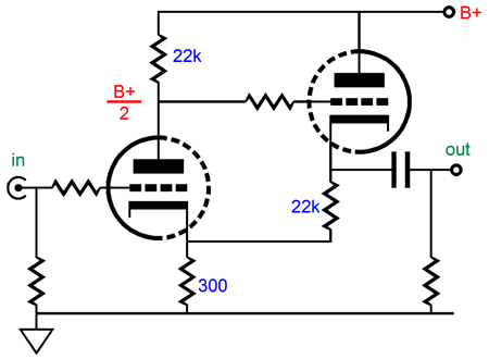
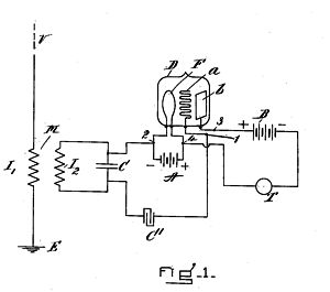
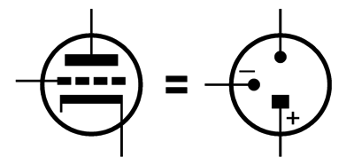
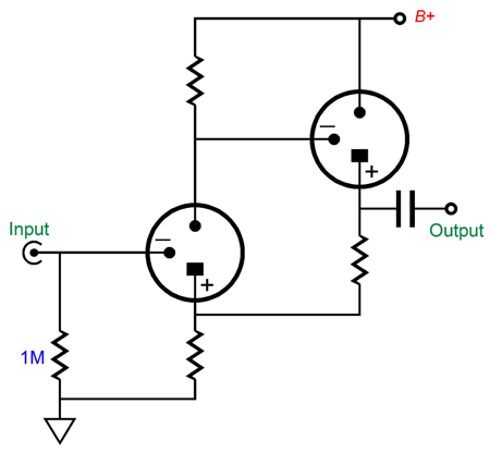
This CCDA-like circuit creates a modest amount of positive feedback, as the cathode follower's cathode resistor terminates into the grounded-cathode amplifier's cathode resistor, not ground. If the 10k resistor were replaced with a 24k resistor, no real positive feedback occurs, as all cathode followers exhibit an insertion loss. In fact, when I first started playing with purposeful positive feedback, I sought only to cancel any signal at the input triode's cathode, much as if a large-valued capacitor had shunted its cathode resistor. In other words, I wanted the gain of a bypassed cathode resistor, but without the capacitor. Why? At the time, I feared the sonic contamination from electrolytic capacitors. Later, I often did use a large-valued capacitor to shunt the cathode resistor after I had nulled the signal at the cathode with positive feedback, working on the assumption that the electrolytic capacitor didn't "see" any signal, so could not sully it. By the way, a triode holds three potential inputs, the plate, the grid, and the cathode, with only the grid inverting the signal. The plate offers a potential gain equal to 1/mu; the grid, mu; and the cathode, mu + 1. In other words, the triode symbol might have been drawn to look more like that of the OpAmp, with inverting and non-inverting "–" and "+" markings. Here is an interesting electronic device:
What is it? Answer, a triode. It appeared in Lee De Forest's 1907 U.S. Patent No. 879,532 for the triode, which he had invented. Sadly, the symbol was created to reflect the device's actual construction, rather than its function.
Well, we could have had the triode symbol on the right. Let's plug it into the two-triode positive feedback circuit.
Now it is easier to see that the input signal inverts at the plate and that the cathode follower's cathode follower's output doesn't invert, so the input triode's cathode will see some recirculating signal, much like a snake biting its own tail.
Music Recommendation: Yosi Horikawa's Wandering The first track mentioned was "Bubbles" by Yosi Horikawa, a Japanese (Osaka) sound designer and electronic music producer, whose music and mad skills are unbelievable. I played the "Bubbles" track and almost fell off my sofa. With my asymmetrical phase-flat tube-based active crossover, I heard the most staggeringly tall stereo image emerge from my two-way loudspeakers. It sounded as if the pellets were bouncing off my ceiling. Each popping sound precisely located and well defined—so much so that I could use a laser pointer to mark the exact location. Amazing, and all the more amazing, when I consider that the 2012 recording is only in 16-bit, 44.1kHz format. The album is embarrassingly short, only four tracks, but well worth hearing. //JRB
Adobe AI Summary: Reasoning and ApproachTo provide a comprehensive summary, I have reviewed the entire document, focusing on its main technical themes, circuit evolution, and practical recommendations. The document is aimed at audio electronics enthusiasts and designers, particularly those interested in high-performance tube amplifier circuits. The summary below distills the key points, technical insights, and practical advice presented throughout the document. Summary of 'Post 646 September 06 2026'Overview: The document explores advanced techniques for extending the bandwidth and improving the performance of cathode-coupled tube amplifier circuits, with a focus on line-stage (preamp) designs. It addresses common challenges such as high-frequency roll-off, Miller capacitance, power supply rejection ratio (PSRR), and practical construction considerations. Key Topics and Insights:
Conclusion: The document is a detailed, practical, and often humorous guide to designing high-performance cathode-coupled tube amplifiers. It balances technical rigor with real-world advice, making it valuable for both experienced designers and enthusiasts seeking to optimize their audio equipment.
Did you enjoy my post? Do you want to see me make it to post 1,000? If so, think about supporting me at Patreon.
|
I know that some readers wish to avoid Patreon, so here is a PayPal button instead. Thanks. John Broskie
John Gives
Special Thanks to the Special 89 To all my patrons, all 89 of them, thank you all again. I want to especially thank
I am truly stunned and appreciative of their support. In addition I want to thank the following patrons:
All of your support makes a big difference. I would love to arrive at the point where creating my posts was my top priority of the day, not something that I have to steal time from other obligations to do. The more support I get, the higher up these posts move up in deserving attention.
If you have been reading my posts, you know that my lifetime goal is reaching post number one thousand. I have 354 more to go. My second goal was to gather 1,000 patrons. Well, that no longer seems possible to me, so I will shoot for a mighty 100 instead. Thus, I have just 11 patrons to go. Help me get there. Thanks.
New URL of the GlassWare website |
||||


%20Large.png)
%20Large.png)
.png)
%20PSRR.png)

.png)
.png)




| www.tubecad.com Copyright © 1999-2026 GlassWare All Rights Reserved |