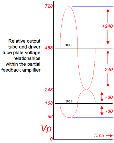
| The trick is to apply a positive bias to the driver stage's grid, so that the higher valued cathode resistor can be used because the grid is now above ground potential. Alternatively, for those cases where idle current against the cathode resistor is too low for the tube we wish to use, the answer is to apply a negative bias to the driver stage's grid via a connection to a negative power supply voltage. But before we can determine the correct bias voltage, we should examine if all these values are at all doable.
Given the 300B's plate voltage of 488 volts at idle, Rfb must find 168 volts at its other end, as 488 - 320 = 168. This value is, in turn, the idle plate voltage of the driver stage. If this tube ceases to conduct entirely, the plate current falls too zero as does the voltage drop across Rfb. This creates a positive going grid voltage that climbs to only -8 volts between grid and cathode for the 300B, which provokes an increase in its conduction, which in turn pulls down its plate to 248 volts where plate swing and grid swing combine to equal 0 volts across Rfb, as the two swings meet each other. (If the plate swings lower than 248 volts, it ends up applying negative going grid voltage to its self that will correct the plate's downward swing by easing up on its conduction. |
Conversely, If the plate swings positive more than 728 volts, it ends up applying positive going grid voltage that will correct the plate's excessive upward swing by increasing the 300B's conduction.) Increasing the driver tube's conduction to 8 mA causes the voltage drop across Rfb to double. Now the 300B's grid to see a negative going voltage that will prompt the 300B to lessen its conduction to where the plate swings up to 728 volts. This means that the voltage across the resistor will be at this point 640 volts! (Resistors have voltage limits and some have pronounced high-voltage distortions; thus, four 20k resistors in series would be a safer route than just using one resistor.) Amazing what ±4 mA can do. Here is a thought experiment, what if four current-output DACs where placed in parallel and their combined outputs were fed into the cathode of a triode that then used resistor Rfb as a plate resistor? This is a cascoding like topology. In this arrangement, the "amplifier" would consist of only one tube, as the 300B would be the DAC's I-to-V converter! If a negative power supply were used along with opto-isolators, the amplifier could be DC coupled throughout, although I would not recommend it for the obvious safety reasons.
DC coupled I-to-V converter |
|
| www.tubecad.com Copyright © 2001 GlassWare All Rights Reserved |

