| Another consideration is the idle plate voltage of 168 volts. Several triodes fit the requirements of handling both 168 volts and drawing 4 mA of current: 5687, 5965, 6SN7, 6N1P, even the 6922, but I really do not want to open that can of worm right now. My first choice would be the 5687, as we need the tube's plate to swing down as far as possible to compensate for the 300B's nonlinearity. However, this tube requires about -9.5 volts bias, which requires a negative power supply that may not be available to correctly bias the tube. My second choice would be the 5965, as this tube only needs -3.5 volts of bias at 168 volts. It also has a wide usable plate swing and it has a fairly high mu (45), which helps to increase the driver stage's output impedance. In fact the 3.5 volt requirement is so close to the 4 volts that 4 mA against 1k yields, that we should lower the value of the cathode resistor to 875 ohms, as this value allows the simpler biasing scheme of just using one grid biasing resistor. Another advantage to this value is that the 5965 is functioning in a cathode follower like topology and no cathode follower ever exactly meets the goal of unity gain. In fact, situation here is made worse by the 300B's low gain. The assumption that the driver stage is working into 0 ohms, is off by about 20k, as the resistor Rfb value dived by the 300B's gain + 1 only reduces Rfb's value to 20k. This 20k plate load effectively subtracts from the 5965's transconductance. In other words, we do get closer to 1 mA per 1 volt of input signal with 875 ohms compared to a 1k cathode resistor. In this example, the we actually get only .6 mA per volt, which means that the driver stage will need to see ±6.6 volts to drive the output stage to 7 watts of output power. Still, ±6.6 volts is a trivial amount of voltage swing for the input tube deliver. So trivial, in fact, that a first stage can be done away with, if the amplifier is used with a active line stage that has a good amount of output swing.
Distortion Our goal is a clean output signal at the loudspeaker. How we get there is not that important. The best approach might be to purposely de-linearize the driver stage so that it can symmetrically compensate for the 300B's non-linearity. To get 7 clean watts, the 300B's grid must see a greater negative voltage swing than a positive swing. In other words, the better tube may not be better.
|
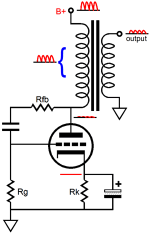
PSRR Problem Everything had been looking so good. One problem that partial feedback amplifier faces is noise. Paradoxically, because it comprises a feedback loop that strives to eliminate stray signals on its plate, such as power supply noise, it relays the noise to the speaker. Remember, in a single-ended amplifier, any signal across the transformer's primary becomes signal across its secondary. If the plate mimics ground and is noise free, the power supply noise becomes a signal across the primary. How do we eliminate the noise from the output? The usual brute force method is to eliminate the power supply noise. Good luck. The other traditional method is to wrap a global feedback loop around the amplifier. Unsavory. The cleaver method is to superimpose the power supply noise on the plate so that the transformer's primary sees no signal. This topic was covered in the second issue of this journal in an article titled "Lowering the Single Ended Amplifier's Output Noise."
Shown below is a hybrid approach to canceling power supply noise from the output. The Plate-channel MOSFET is fed a portion of the power supply noise, which is dutifully relayed to the 300B's cathode. The advantage this topology enjoys over the two capacitor voltage divider is that it is easily adjustable should the tubes drift over time. |
|
| www.tubecad.com Copyright © 2001 GlassWare All Rights Reserved |