| John Broskie's Guide to Tube Circuit Analysis & Design |
20 December 2006
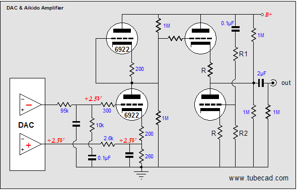
Held at Beukenhof, in the Netherlands, from November 30th to December 3rd of this year, the European Triode Festival (ETF) has come and gone. Sadly, unlike last year, I was not able to attend the event. Nonetheless during the end of November and the beginning of December, as each day of the festival passed, my thoughts were drawn to all that I was missing: lively conversations, great beer, tube-related presentations, tube equipment shootouts, and the chance to see again so many tube enthusiasts and friends who made last year’s ETF so memorable for me. Heck, I’ll even add "seeing some snow" to the list. My friend Arthur Spieker in the Netherlands made his first trip to the ETF and his e-mail to me afterwards smoldered with eagerness and enthusiasm. I know the feeling well, as I felt the same way last year. The ETF is the best audio event for anyone interested vacuum tubes and fraternity; if only we had something comparable in North America. For unlike a typical stereo show, the ETF is a true celebration, not a marketing tool. And I was not there! Alas. But there is always next year. (By the way, there are several requests to kill the Wikipedia entry for the ETF; for example, "Very small gathering of vacuum tube audio enthusiasts. Appears to have little media coverage, and the article itself indicates it only draws about 100 participants per year." It is a good thing that I do not know how to spell microcephaly... The Vienna Circle is not as well attended or received as much media coverage in the 1920s, yet... Cast your vote for the ETF's inclusion at Wikipedia.) Periklis mated a cheap Chinese DAC to an Aikido circuit from this journal (blog 77) and housed the project in a wood case from Ikea.
As soon as I get more details and links to further information, I’ll post it here. (I planned on holding off mentioning the Aikido-based DAC until it was posted elsewhere, but I have gotten enough requests for more information that I felt I shouldn't hoard the details I have so far.) Of course, such a project is a big and complex undertaking, with many factors contributing to its success; but at the very least, we know that the Aikido portion of the DAC did not let down the undertaking. (Considering that Periklis tells me that he used whatever electronic parts he had on hand, some better and sone worse than they should have been, his winning DAC is all the more impressive an accomplishment.)
By the way, I did get a chance to actually hear a Broskie-cathode-follower-based DAC. A long time reader, Dr. Dean, was kind enough to send me his DAC project for a sonic evaluation. His DAC is still a work in progress and it greatly interested me, as it uses Wolfson DACs (WM8740). Unfortunately, the unit held a power supply grounding problem, so it hummed quite badly. Nonetheless, there was an obvious rightness about the sound that I immediately heard and appreciated. Once again, very much like the Aikido, there was that surefooted, at-ease, confident sound. Crazy adjectives, I agree, but when you hear it, you know exactly what I am talking about and you'll miss dearly when it is absent. My plan is to fire up the soldering iron and build my own tube-output DAC next month. (Christmas and the PCB sale will keep me busy enough this month. Speaking of the PCB sale, not many 9-pin Aikidos remain: just seven mono and nineteen stereo PCBs.) My plan is to use a balanced-voltage-output DAC, such as the Wolfson WM8740 and a modified Aikido line-stage amplifier.
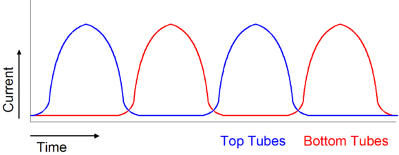
Crossover notch distortion (continued) Once again, forget the glib ads in shinny audio magazines, class-A is pitiless, requiring many output devices and big power supplies—doubly so for tube-based class-A power amplifiers. Consider this: in the USA, the wall socket relies on a 10A or 15A circuit breaker in most houses. So, first subtract the current needed to light the room and power the rest of the stereo system. (For example, three 100W light bulbs will wick away 2.5A from the potential current limit.) Now, let’s say that we are left with 10A useable amperes of current, which against 120V equals 1200W. Isn’t 1,200W a huge amount of wattage? No, not really, as each channel will only get 600W to play with and, once we have factored in the power supply conversion losses and the theoretical maximum class-A efficiency limit of 50%, we end up with 250W. Well, what’s wrong with 250W? What’s wrong is that, with vacuum tube output devices, we would be lucky to get a maximum efficiency of 25% in class-A, so our 250W degrades into 125W. Yes, 125W is a lot power for any type of amplifier, but how many power tubes would be needed to realize that much power? Well, we know that at 25% efficiency the power amplifier’s output s will have to dissipate 500W at idle, which means twenty 25W power tubes, such as the EL34, or fourteen 40W tubes, such as the 300B or KT88 (rounding up to even numbers). However, power tubes do not live long at maximum dissipation, so we should back off by at least 25%, rendering 30W for a 300B or KT88; thus, eighteen 40W tubes will be needed. Ok, so it is a bit crazy to run eighteen KT88s per channel, but 125W of class-A glory is worth it. Oh, but did I forget to mention that you can't run that many KT88 tubes under our wall-current limit? You see the output plate dissipation is only part of the overhead: there’s the issue of the heater’s dissipation and current draw. For example, 36 KT88s draw 57.6A of heater current, which against 6.3V, equals 363W of dissipation, assuming AC voltage, as DC voltage would also incur the power supply losses. In fact, even the AC heater voltage approach suffers from the transformer losses due to self heating from core losses and wire resistance. Therefore… enough, enough—I cannot take any more reality without the aid of drugs or some glossy ads in audio press. Speaking of glossy ads, do not be swayed by the marketing message that you can somehow create a true class-A push-pull amplifier by using sloppy power output tubes (6AS7s for example) that are so nonlinear at low currents that they cannot be turned off completely. You can't. Honest-to-God class-A operation means that both sets of output devices contribute meaningfully to the output. Having one-half of the output tubes leak a trickle of current during half of the waveform only drags down the output stage and contributes nothing of sonic value—of course, advertising copy is another story.
The Butler amplifier and other remedies
The idea here is that both the transistor and the vacuum tube are non-linear devices, but that both combined create a more linear device. The triode’s grid is attached to its plate and the triode becomes a diode that connects to the transistor’s base. The triode/diodes receives the same phase input signal, but with a DC offset that sets the idle current through the output transistors.
Does this scheme work? I don’t know. The Butler amplifier is well reviewed, however, so maybe it does work.
Another push-pull output stage technique
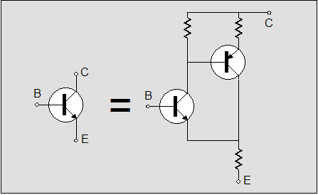
The schematic shows how a single transistor can be replaced by a compound circuit of two transistors and a few resistors. Effectively, the compound circuit defines a unity-gain buffer which achieves a high feedback ratio, greatly improving the linearity and lowering the output impedance. The downside to this circuit is possible high-frequency instability. Now the trick is to sample the current conduction of both output transistors.
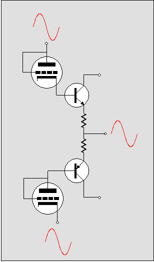
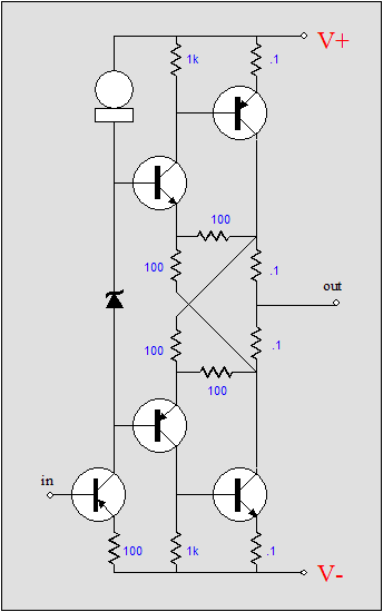
The above schematic shows how each input transistor monitors the current flow through the two 0.1-ohm resistors, and thus through the two output transistors. Does this modification to the standard compound output stage work? Yes, it does. If I remember my SPICE evaluation of the circuit correctly, it lowers the distortion by about 20 dB. Don’t see it? Try imagining an OTL output stage and then apply the technique. (I like to imagine a tube guru—of the part-worshipping sect—scratching his head or, what is more likely, shaking his head with disgust, as everyone knows that real tube gurus don't do topology.) Remember the whole point is to sample the current conduction of both the top and bottom triodes at the same time. Still don’t see it? Okay, here it is:
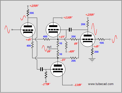
Note that both input triodes see opposite-phase input signals, which means that phase splitting is needed. In addition, note that the 10-ohm current-sense resistors will work well with headphones, but are too high for loudspeakers. (Actually, I imagined using many triodes in parallel, each with its own 10-ohm resistor.) Also note that two 400-ohm cathode resistors on the left side of the schematic equal the one 200-ohm cathode resistor on the right side of the schematic, so the two input triodes bias up the same, with the same DC voltage on their grids. Since this topology isn’t mirror symmetrical and since no P-version of the triode exists, this new topology could never be covered by the original patent (unless of course enough of the OJ-Simpson-trial jurors could be rounded up again). So, first one to the patent office is a winner. (Now, for the really sneaky trick, replace all the output triodes with N-channel MOSFETs or NPN transistors...) For the rest of us, this circuit is another interesting tube circuit from the TCJ, just one out of hundreds. In fact, this OTL amplifier may never get built, unless the ETF decides to have an OTL shootout next time that is. //JRB
|
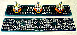
The TCJ Stepped Attenuator The center knob controls both channels, and offers six large decrements; the flanking knobs offer six fine decrements for each channel, creating a volume control and balance control in one easy-to-use stepped attenuator. This clever attenuator uses fewer resistors (only 32) than would be expected from a conventional 32-position stepped attenuator, as two series attenuators would need a total of 72 resistors; and two ladder attenuators would require 140 resistors. In addition, the PCB holds dual sets of resistor pads, one wide and one narrow, so that axial (composition, wire-wound, and film) and radial (thick-film and bulk-foil) resistors can be used without extra lead bending. Although designed to go with the Aikido amplifier, it can be used anywhere a high-quality attenuator is needed, whether passive or active. For example, it would make a first-rate foundation to an excellent passive line box. Visit our Yahoo Store for more details: http://glass-ware.stores.yahoo.net/
Support the Tube CAD Journal & get an extremely powerful push-pull tube-amplifier simulator for TCJ Push-Pull Calculator
TCJ PPC Version 2 Improvements Rebuilt simulation engine *User definable
Download or CD ROM For more information, please visit our Web site : To purchase, please visit our Yahoo Store:
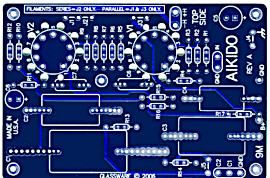
High-quality, double-sided, extra thick, 2-oz traces, plated-through holes, dual sets of resistor pads and pads for two coupling capacitors. Stereo and mono, octal and 9-pin printed circuit boards available.  Aikido PCBs for as little as $24 http://glass-ware.stores.yahoo.net/
The Tube CAD Journal's first companion program, TCJ Filter Design lets you design a filter or crossover (passive, solid-state or tube) without having to check out thick textbooks from the library and without having to breakout the scientific calculator. This program's goal is to provide a quick and easy display not only of the frequency response, but also of the resistor and capacitor values for a passive and active filters and crossovers. TCJ Filter Design is easy to use, but not lightweight, holding over 60 different filter topologies and up to four filter alignments: While the program’s main concern is active filters, solid-state and tube, it also does passive filters. In fact, it can be used to calculate passive crossovers for use with speakers by entering 8 ohms as the terminating resistance. Click on the image below to see the full screen capture.
Tube crossovers are a major part of this program; both buffered and un-buffered tube based filters along with mono-polar and bipolar power supply topologies are covered. Available on a CD-ROM and a downloadable version (4 Megabytes). |
|||
.png)


| www.tubecad.com Copyright © 1999-2006 GlassWare All Rights Reserved |