| John Broskie's Guide to Tube Circuit Analysis & Design |
|
Once again, the Cathode-Coupled Amplifier
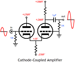
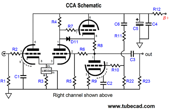
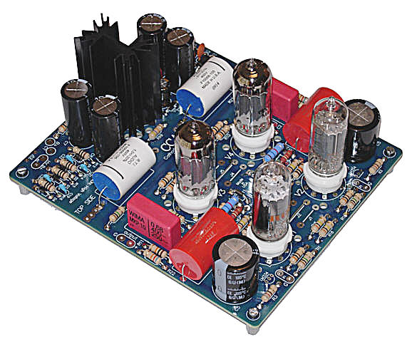
1999/tubecircuits/Common-Cathode Amplifiers I even have a PCB for the cathode-coupled amplifier, the GlassWare CCA design, which uses an Aikido cathode follower as an output stage and which scrubs away the power-supply noise riding on the cathode-coupled amplifier's output signal.
The CCA line amplifier presents no phase inversion and offers a very low input capacitance, as the typical Miller-effect capacitance is sidestepped; the input triode's plate does not move with the input signal. In addition, it produces little distortion and a low output impedance. Yet, few have bought the PCB or kit. (One day, the word will get out and I will instantly sell out of the remaining boards. I am often startled by how a certain PCB can languish on the shelf, then instantly sell out in a day or two, accompanied with breathless e-mails asking how many hours before the kits arrive. This happened recently with the H-PS-1 low-voltage regulated power supply. Word got how good the Squeezebox line sound with it in place of the cheap switching wallwart.) So, if I have already covered the cathode-coupled amplifier, why am I returning to this topology? I have been corresponding with a reader who wants to modify an existing tube line stage he owns that holds three tube sockets mounted on the chassis top and is hardwired inside. He is keen to get the most performance possible from these three tubes, as he has just listened to a friend's octal Aikido All-in-One and now his line stage amplifier doesn't sound nearly as good. Good man. In fact, a stereo Aikido line stage can be made from just three tubes.
The plan requires that the input triode's plate resistor split the B+ voltage (and by extension, the power-supply noise). Then the Aikido cathode follower will null the 50% of the power-supply noise that the input stage leaks. The plate resistor should be roughly equal to rp + (mu + 1)Rk. I could stop right there, as such a line stage would sound much better than what he had been running before (a grounded-cathode amplifier followed by an SRPP stage and a global feedback loop), but but he wished to retain his super-expensive trio of NIB, NOS tubes: one 12AX7 and two 12AU7s. The problem with using a 12AX7 as the input tube in the three-tube Aikido is that it creates far too much gain, +34dB, as gain equals mu/2. Of course, replacing the 12AX7 with one extra 12AU7 would solve that problem. Still, his request for help got me thinking about my old friend the cathode-coupled amplifier as a possible candidate.
Aikido Cathode-Coupled Amplifier
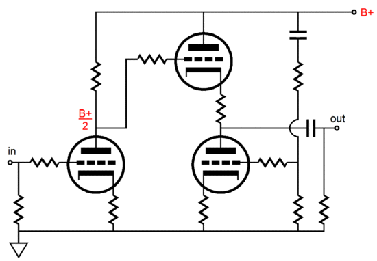
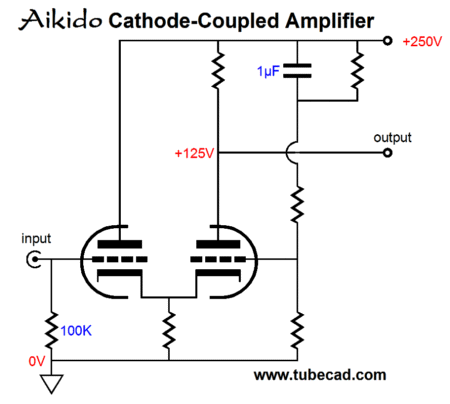
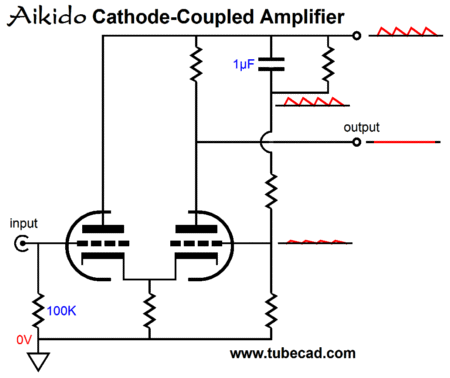
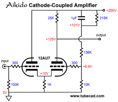
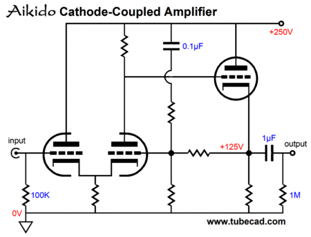
The right triode sees two input signals: the one at its cathode from the left triode and the one from the connection to the B+ through the two-resistor voltage divider and the 1µF capacitor. By carefully selecting resistor value, a deep null in power supply noise at the circuit's output can be achieved.
If the 1µF capacitor has shunted the bottom of the three resistors in series (the way 99.9% of tube gurus would do it), the cathode-coupled amplifier's poor PSRR would result in most of the power supply noise exiting with the output signal. But by injecting the optimal amount of power supply noise to the right triode's grid, we can provoke an anti-phase output signal just great enough to null the power supply noise at the plate, thereby producing a noise-free output signal. The exact ratio will depend on the tubes used the plate and cathode resistor values. Now, let's fill in a design example's values. (Of course, this is just one of a near-infiite number of possible examples. So, yes, a 6SN7 could be used in this topology, as could two ECC99s or two 300Bs or two 834s. "Topology is separate from parts," which I would have tattooed on my arm, if I ever got that drunk, drug addled...or senile.)
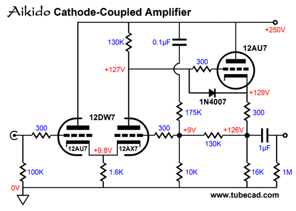
Note how high the cathode voltage and the right triode's grid voltages are in this design example. With a cathode-to-plate voltage of 240V, the leftmost triode must see -10Vdc on its grid to establish an idle current flow of 5mA, whereas the rightmost triode's 115V cathode-to-plate voltage requires only -3.1Vdc of grid voltage (10V - 6.9V) to match the 5mA of current flow. The next thing to note is the absence of a coupling capacitor. Where is the coupling capacitor? I left it off the schematic purposely, as an external load resistance will force a different set of resistor values for the two-resistor voltage divider. This makes for a poor line-stage amplifier, as a good tube-based line-stage amplifier should work well with a large range of load impedances, say from 10k to 100k. Of course, we could target the right values for 31.6k, relying on other load impedances being close enough for government work. (Speaking of which, a friend of mine was once coming back into consciousness and as the anesthesia wore off, he heard the army doctor say, "Okay, let's stitch him up: I'm getting hungry for lunch; besides that's good enough for government work." ) The better path is not to load down the cathode-coupled amplifier's output with any resistive load.
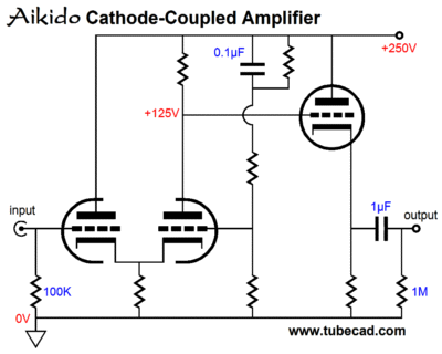
The cathode follower presents a near-infinite load impedance to the cathode-coupled amplifier and offers a low output impedance. Note how triodes are used, so the reader with the three-tube line-stage amplifier would be happy, as three dual-triode tubes could be used. Now the question is how can use his two 12AU7s and one 12AX7? The 12AX7 makes a poor cathode follower in a line-stage amplifier, as it draws a miniscule amount of current. Nor could it be used as the input triode with a 12AU7 partner, as its required cathode voltage would prove far too low for the 12AU7. This leaves the centermost position. Well, here is where the 12AX7's high mu and low cathode-to-grid voltage come in handy. Wait a minute; I though the 12AX7 created too much gain? True enough, but if we add a negative feedback loop, the extra gain would become a feature.
The feedback is taken at the cathode follower's cathode, which provides the added advantage of establishing DC feedback of the 12AX7's operating voltages. This is hugely important, as the previous circuit (with a 12AU7- and 12AX7-based cathode-coupled amplifier) is a perfect example of a circuit that can function flawlessly in SPICE but fall on its face in reality. With the 12AU7 drawing five times more current than the 12AX7, the 12AU7 need only move a small percent of its design targeted idle current to throw the 12AX7 way off its design voltage targets. The DC negative feedback checks such DC deviant behavior. Nonetheless, this circuit retains the Aikido power-supply noise reduction technique.
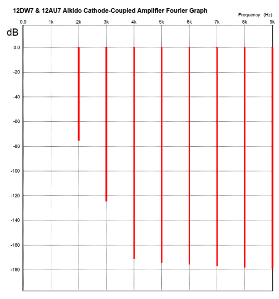
I know that this circuit looks a bit complex, but even with point-to-point wiring, it should not be that big a deal to build. The next question is how well does it perform? In SPICE it produces a lovely Fourier plot of harmonics. With a load of 47k and 1kHz and 1Vpk, the following graph was produced. Even if reality is only one tenth as good, the results would be eagerly welcomed.
Aikido Cathode-Coupled Amplifier Variation
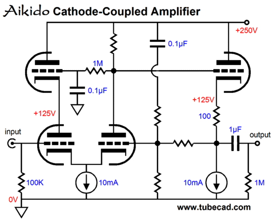
If the same 12AU7 & 12AX7 pairing is used, with the 12AU7 triode as the input triode (the left riode in the differential pair), the 12AX7's grid voltage will be much lower, as a result so, too, must be the feedback ratio, which means a higher gain at the output will result. This might just be feature in some applications, but for line-stage amplifier use, a better choice would be to use the same medium-mu triode throughout, say two 6CG7, 6SN7, 12AU7, 12BH7, 5687, ECC99 or, even triode-connected EL84 and EL86 tubes. Why? Using medium-mu triodes will develop a higher grid voltage for both cathode-coupled amplifier triodes, which will allow more feedback to be used, resulting in less gain at the output. The two constant-current sources were added to make for the lower cathode-to-grid voltage on the cathode-coupled amplifier input stage, but a negative power supply could be used instead. In fact, -12Vdc might prove sufficient. I would use the -12V negative power supply to power the cathode-coupled amplifier's tube's heater and give the top two triodes a heater power supply referenced to 140Vdc. Yes, two heater power supplies is a pain, but so is exceeding a tube's maximum cathode-to-heater voltage, usually only 100Vdc. I better stop before I catch my breath and write another section. Next Time
//JRB |
|
E-mail from GlassWare customers:
And
High-quality, double-sided, extra thick, 2-oz traces, plated-through holes, dual sets of resistor pads and pads for two coupling capacitors. Stereo and mono, octal and 9-pin printed circuit boards available. Aikido PCBs for as little as $20.40 http://glass-ware.stores.yahoo.net/ Only $12.95 TCJ My-Stock DB
Version 2 Improvements *User definable Download or CD ROM www.glass-ware.com |
||
| www.tubecad.com Copyright © 1999-2011 GlassWare All Rights Reserved |
