| John Broskie's Guide to Tube Circuit Analysis & Design |
| 06 October 2013 Circlotron Revisted  C. T. Hall's Patent of the Circlotron Circlotron Gaps
Well, there is always something new under the sun, if you know where to look. For example, with a few more advancements, carbon nanotube field-effect transistors (CNTFET) will become available and they could be used in a Circlotron amplifier. Today, we can buy Silicon Carbide (SiC) transistors and MOSFETs, which can also be used in a Circlotron amplifier. True, these are just new devices being plugged into an old topology. So, are there any real gaps, topological gaps, to be filled? Indeed, yes.
Current-Out Circlotron A few years ago, when I was obsessed with current-out amplifiers, I wondered what a current-out Circlotron power amplifier would look like. The circuit I came up with was based on the topology I created for blog 137.
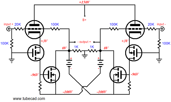
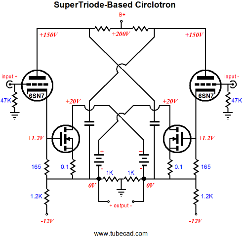
The above Circlotron is a voltage-out design that uses two negative-feedback loops to set the fixed gain. (The output devices are assumed to be BUZ901 power MOSFETs.) If we subtract the feedback loops, the output MOSFETs run wild, developing an output swing based on the load resistance and the MOSFET's transconductance. The following circuit removes the two negative-feedback loops.
A balanced input signal is applied and the MOSFETs see this signal at their gates, but voltage-shifted down. After running many SPICE simulations, I was disheartened, as the results were poor, very poor. Different MOSFET types didn't help. I, then, assumed that the MJE350 PNP transistors were gumming up the works, so I tried other types, to no avail. Still convinced that the transistors were somehow at fault, I ran some simulations on the following circuit, which uses two input transformers in place of the PNP transistors.
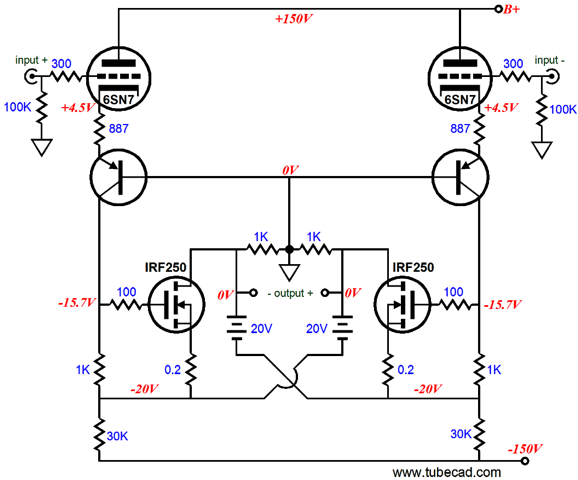
Once again, the results were poor. This troubled me greatly, as a similar circuit, shown below, yielded fantastically good results.
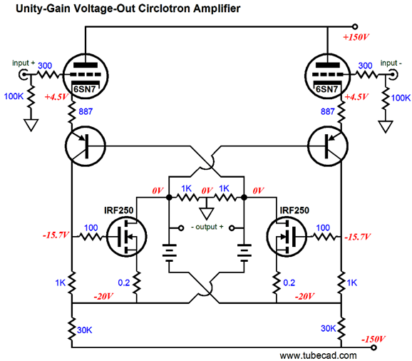
A big, balanced, input signal is applied and the MOSFETs see this signal voltage-shifted down at their gates; and the PNP transistors bases no longer attach to ground, but to the the output terminals. This circuit is a unity-gain power buffer, which explains why a huge balanced input signal is required, as this buffer provides no voltage gain. So, what went wrong with the current-out version? If we pause and pull back, we see that what drives all of these designs is the MOSFET's transconductance, which the input signal stimulates into action. In the case of the current-out Circlotron, the small input signal had to provoke big output voltages and current swings from the MOSFETs, as they worked into the loudspeaker's 8-ohm impedance. But in the case of the voltage-out Circlotron, the huge input signal didn't need to create voltage amplification, only current delivery. Thus, we were not close to comparing apples to apples, as the unity-gain buffer enjoyed a huge advantage by seeing a huge input signal, which it could use in a degenerative fashion to force its output to conform to accurately. Imagine that you are given $10,000 to build a nice tool shed with. Now, imagine that you are given $300,000 to build a tool shed, the same size, but nicer. Which project would would be more likely to turn out well? In other words, if a current-out Circlotron were designed to accept a huge input signal, what improvement in performance might be had, considering that it could use that huge input signal?
Hybrid Circlotron Variations
A typical power MOSFET, on the other hand, delivers gm of many amperes per volt and can release many amperes of current. Thus the appeal of combining the two technologies. We can simply cascade the MOSFET after a triode, so the triode delivers the MOSFET its input signal, as is done in the following design.
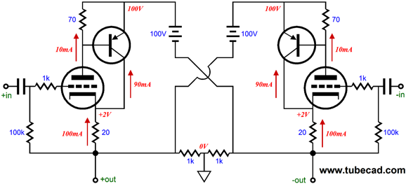
This is not the only way configure a hybrid Circlotron, however. for example, we can use two PNP transistors with the two triodes, as the following circuit shows.
The PNP transistor conducts nine times more current than the triode (a 6DJ8) at idle, but it is the triode that is in charge of the PNP transistor. If the transistor conducts too much, it will turn off the triode, which in turn will turn off the PNP transistor. If the transistor conducts too little, it will force the triode to increase its current conduction until the PNP transistor turns on and conducts sufficient current to establish the necessary base-to-emitter voltage for the PNP transistor. In other words, this is a self regulating circuit, wherein the triode's current swings are small compared to those of the PNP transistor. The above design would make an excellent balanced headphone amplifier output stage for low-impedance loads. Unfortunately, this topology will not work well with driving speakers, as the PNP transistor will see far too much emitter-to-collector voltage. In the previous hybrid circuit, this was not an issue, as the MOSFETs received their own low-voltage floating power-supply rails. How do we do this with the PNP-transistor-based design?
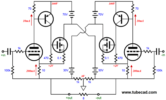
The above circuit uses two B+ voltages, 30Vdc and 100Vdc, with the power MOSFETs using the lower voltage. The PNP transistor still strives to maintain a fixed base-to-emitter voltage and the triode still receives the input signal and controls the MOSFET's output. Mind you, this schematic is only for instructional purposes, as the MOSFETs are missing their essential gate-stopper resistors and the two 10-ohm cathode resistors are excessively large in value. Nonetheless, the topology is sound.
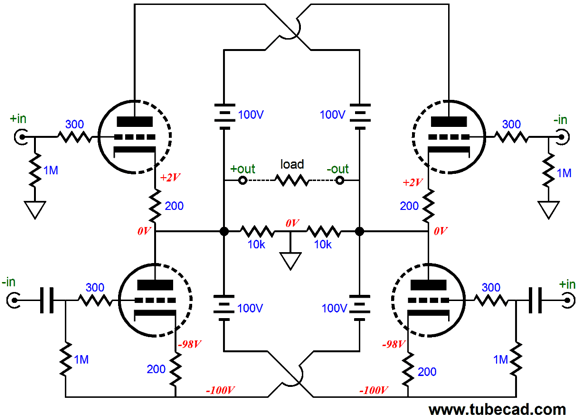
Circlotron Puzzler
In the above doubled-up Circlotron circuit, how much larger or smaller should be the signal delivered to the top triodes versus the signal amplitude the bottom triodes will see?
Next Time
//JRB |
I know that some readers wish to avoid Patreon, so here is a PayPal button instead. Thanks.
John Broskie
E-mail from GlassWare Customers
High-quality, double-sided, extra thick, 2-oz traces, plated-through holes, dual sets of resistor pads and pads for two coupling capacitors. Stereo and mono, octal and 9-pin printed circuit boards available.  Aikido PCBs for as little as $24 http://glass-ware.stores.yahoo.net/
Support the Tube CAD Journal & get an extremely powerful push-pull tube-amplifier simulator for TCJ Push-Pull Calculator
TCJ PPC Version 2 Improvements Rebuilt simulation engine *User definable
Download or CD ROM For more information, please visit our Web site : To purchase, please visit our Yahoo Store: |
|||


| www.tubecad.com Copyright © 1999-2013 GlassWare All Rights Reserved |