| John Broskie's Guide to Tube Circuit Analysis & Design |
| 25 February 2014
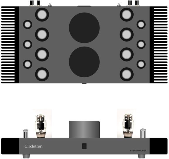
Circlotron & Impedance-Multiplier Circuit The missing end of the tale concerned the use of a gain-clone chip amplifier, such as the LM3886 or LM4780, with an otherwise all-tube-based Circlotron. The sonic glory of glass wedded to the brute strength of silicon.
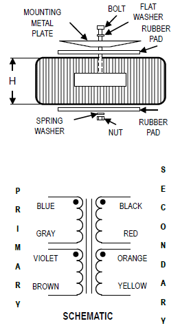
The Circlotron circuit has been beaten to death here, so I will not go over all the details again here. Suffice to say, the Circlotron is super popular, but it does run into some problems. Problems? I thought the Circlotron was perfect. I bet you did. Sad to say, but no circuit is perfect. The smaller problem of the two is that while the Circlotron eliminates the need for an output transformer, a heavy and expensive device, it does requires a fairly complex power supply, as each channel must use two floating high-voltage power supplies in addition to whatever power supplies are needed for the input and driver stages, heaters, and negative-bias voltage that the output tubes will need. The second, bigger, problem is that not that many output tubes are available. Unlike a transformer-coupled amplifier, which can be made with 2A3, 6B4, 6BQ5, 6L6, 211, 300B, 845, 6550, 8417, EL34, KT66, KT77, KT88, KT100, KT120... the Circlotron only finds the 6AS7, 6C33, and EL509/6KG6 tubes. This is a pity, as no one will claim that a 6AS7 is anywhere as linear, as good-sounding as a 300B triode. (I remember being told that since the 6AS7 and 2A3 share similar looking glass envelopes, they must sound the same. Sure, just as Bud Lite and Odell IPA must taste the same, as their bottles look so similar.) On the other hand, if we build a Circlotron based on the 300B, then we will have to use that heavy, expensive output transformer. Or would we? Many forget the autoformer, which is like a transformer, but holds a single winding.
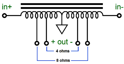
The autoformer would replace the usual two-resistor voltage divider on the Circlotron's output, as the autoformer's center tap can be grounded, thereby ground referencing the output stage. And much like a transformer, the autoformer will make the 8ohm load appear as a much higher load impedance to the output tubes. Still, a good autoformer is just as big, expensive, heavy, and rare as a good output transformer. Let's get down to fundamentals, such as grid voltages and plate voltages and currents. The wonderful 300B triode, with 0V grid volts and a cathode-to-plate voltage of 160V, can draw a mximum current of about 250mA. Not nearly as much as we would like. Under the same conditions, in contrast, a 6C33 can draw over 2A! Nonetheless, 250mA is not a trivial amount of current. Two 300B in parallel would deliver 500mA, which would equal 1W into an 8-ohm load, as I² x R = W, where I is average current or Ipeak/1.414. Seriously, just one measly watt? Don't laugh... actually, I changed my mind, do laugh, as Bruce Rozenblit has built a 1W OTL that uses four 300B per channel. Yes, four 300B triodes and 1W of output. His effort is a single-ended affair, idling at 500mA, so he only got 1W of output. Okay, stop laughing. Perforce, his must be the best sounding amplifier in existence. How so? Every devoted audiophile knows the following formula, if only intuitively: Sound = $/W, where $ is the cost and W is that amplifier's power output. For example, a $27,000 amplifier that puts out 27W, will develop 1,000$/W, but an $300 amplifier that puts out 30W, will only develop 10$/W—and will sound 100 times worse because of it, as everyone knows that 1,000$/W is 100 times more than 10$/W. (Sarcasm alert!) But as the Circlotron is a push-pull affair, it can only fully turn on half of its output triodes at once, as other half turn off, the so the same 1W limit results. Of course, given the same peak current flow, a higher-impedance speaker would receive more watts; for example, a 200-ohm speaker would produce 25W with a peak current flow of 500mA. But since 200-ohm speakers are rare, if not truly nonexistent, the best workaround would be to use a circuit that makes an 8-ohm speaker appear as a higher impedance load, so that the four 300B tubes in a Circlotron amplifier could see a more forgiving loadline. Such a circuit is the impedance-multiplier circuit (IMC). As two 300B max out at a total of 500mA, the IMC will have to add 2A of peak current flow to get 25W out of an 8-ohm load. Now, 2.5A against 8 ohms equals 20Vpk, thereby delivering 25W, as V²/R = W, where V equals the average voltage or Vpk/1.414. Since the IMC must deliver four times more current than the 300B-based Circlotron, the IMC's multiplier ratio must be equal to 4 + 1, or 5, so the 8-ohm load will appear as a 40-ohm load to the Circlotron. In other words, the 300Bs think they are attached to a 40-ohm load, as that is the loadline they work upon.
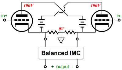
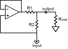
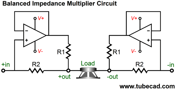
Now, the only problem that remains is to design a balanced IMC that will accept a differential set of input signals and present two balanced outputs. As has been shown here many times before, making an unbalanced IMC is fairly easy. All that is required is a unity-gain-stable power amplifier and two resistors. (In fact, a unity-gain power buffer can replace the power amplifier.)
The balanced IMC isn't that much more difficult to imagine, as we can just use two unbalanced IMCs with the speaker falling in between the two.
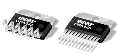
The real-world problem is that unity-gain power amplifiers, which are readily available in chip-amp form, are rare. Bur-Brown designs, such as the OPA549, are unity-gain stable, but cost more than twice as much as the more common LM3886; in addition, the OPA549 can only see a maximum power-supply differential of 60V, i.e. +/-30V, whereas the LM3886 can withstand up to 84V, i.e. +/-42V. Nonetheless, the OPA549 offers some real advantages, such as a user-selectable current limit. (And I wouldn't be at all surprised to find it better sounding as well.)
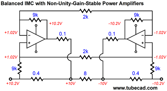
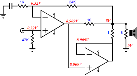
What do you do if you wish to use the LM3886 or some other non-unity-gain-stable chip amplifier? The workaround is to let the amplifier develop gain, but throw away a matching amount of its input signal.
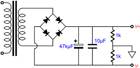
Note how each amplifier sees its 10.2V input signal reduced to a tenth. Also note how the two amplifiers are set up to develop a voltage gain of 10. (If you are having a hard time seeing either of these, then imagine that the two 2k resistors have each been replaced by two 1k resistors in series, with a ground connection made at where the two resistors meet.) Since 9k resistors are hard to find, we can replace them with 10k resistors; 9k were used to make the voltage relationships clearer. Not shown is the rail voltages for the IMC amplifiers. In this example, where the total power output is 25W, +/-15V would prove adequate, as each of the IMC's power amplifier need only swing +/-10V at its output. No doubt, your first thought is to assemble a bipolar power supply based on a full-wave, bridge, center-tapped rectifier circuit, which uses a center-tapped secondary. But pause and consider this: the load, i.e. the speaker, never attaches to ground, only to the two outputs from the balanced IMC. So, why bother with a robust ground terminal? In other words, why not use a mono-polar power supply that is referenced to ground through a two-resistor voltage divider?
Such a power supply would never work with an unbalanced power amplifier, as the 1k resistors would be series with the 8-ohm speaker, defining a 500-ohm ground connection. But a balanced output is an altogether different animal. Okay, John, but other than halving the number of required power-supply capacitors, what advantage does this mono-polar power supply offer? First of all, it also halves the bipolar power supply's effective-series resistance, as two power supply capacitors are not in series. Second, most power toroidal transformers offer two equal and independent secondaries, which are usually wired in series to create a center tap. But we could keep them separate, so each channel gets its own secondary and mono-polar power supply.
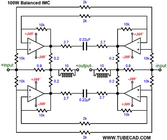
Okay, John, that's nice. Although this design is 25 times better than the 1W version, 25W is still not that much power. So how do we get more power, say 100W? Getting more power is easy enough: just increase the balanced IMC's impedance ratio and bump up its power supply voltage. For example, if we replace the 0.4-ohm IMC resistors with 0.9-ohm resistors, the IMC will increase the 8-ohm load's impedance by tenfold, 80 ohms. And if this allows twice the voltage swing, up to 40Vpk from 20Vpk, the power output will quadruple to 100W. This would require a mono-polar power supply voltage of 56V to 60V for the IMC. Understand this, while the Circlotron believes that it is attached to an 80-ohm load, each of the two power amplifiers within the balanced IMC think that they are attached to a 4-ohm load. What? Each power amplifier must put out the equivolent amount of current that a 4-ohm speaker would draw if it were attached to the power amplifier and terminated into ground. (Think about this: at the midpoint of the speaker's voicecoil no voltage exisits, but much current flows past, just as if two 4-ohm resistors were placed in series and +20V applied at one end and -20V applied at the other end.) To lighten the load, I would use four power amplifiers in the balanced IMC. Here is one possible configuration. The LM4780 would be a good choice, as they hold two power amplifiers.
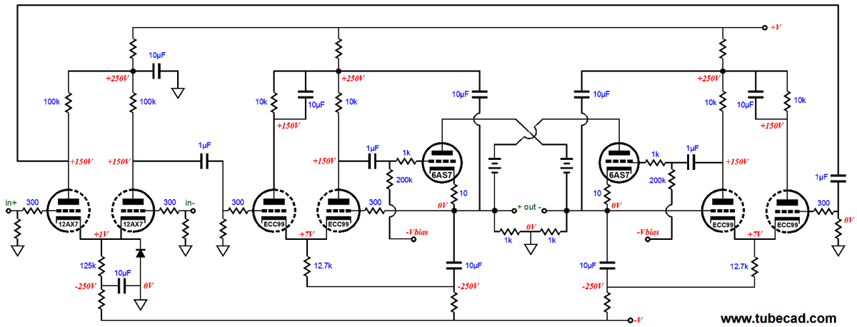
Still, I wouldn't do it. Why not? I like the idea of the 300B contributing a fifth of the output current, but not one tenth. Maybe I am wrong here (and I would be happy to discover it), but that just seems to me a move too greedy. By the way, I must mention that we can run our 300B-based Circlotron in class-AB and that we can bump the B+ voltage to some value more vital, say 250Vdc. But what will be required, no matter what the B+ voltage or idle current, is a lot of negative feedback. Why? The 300B output impedance in a Circlotron circuit is very high, compared to what a 6C33 would present in contrast, so the NFB is needed to lower it.
How could a negative feedback loop be applied? Well, the schematic above shows just one example.
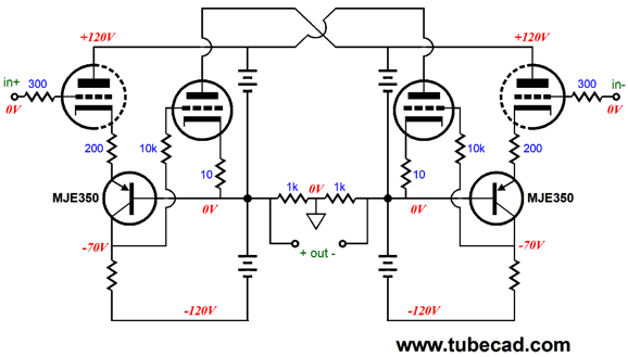
A quick Google search will of this web site will reveal many more possibilities, such as the one above.
Book Review: Tubes and Circuits, by Bruce Rozenblit If only it were so; with rare exception, most super-secret schematics are as dreary as last year's newspapers. Moreover, exposing your commercial designs can only hurt sales. Why? Because people like me will offer modifications, which implies that the circuits were not perfect to begin with (as if any circuit were perfect), which can only introduce doubt, the last thing a sale needs. Audio sales require true believers. And the last thing that I want to do is hurt either his equipment or book sales. It is hard enough making a living in this business. At the same time, I cannot lend my unalloyed recommendation of this book. First of all , I welcome any new book on the topic of tube circuits, as most of the great books on this topic where long ago expunged from public libraries. Moreover, many of the old great books thought audio such a trivial matter that they tended to only give a quick gloss, rather than a prolonged and deep account of the subtleties involved. At the same time, I know that we all have limited budgets, that we all wish to get the most bang for our buck, which is why I must fall short of a full endorsement. For example, only 45 pages out of this book's 268 pages are really devoted to tube circuits. What are the rest of the pages filled with? Well, it's an odd mix. He begins with a chapter on basic circuit science, which I quite enjoyed reading. He, then, follows it with a chapter titled, "What is Electricity?" This was an odd read, filled as it was with short, choppy sentences such as the following:
One simple sentence after another, it was as if I were reading something my 11-yearold son had written. (Well, actually such a slander cannot stand, as my son writes a far more complex and embellished prose, which unfailingly delights his teachers, who find his prose style embodying a mature style, a style far beyond his years, as his far-fetched diction and complex syntax offer a sharp contrast to the impoverished diction and simple, short sentences of his classmates. Semicolons, colons, and dashes—all make an appearance in his writings. Almost instinctively, he seems to know what John Erskine pointed out long ago: that in writing, unlike sharpening a pencil, you make a point by adding, not by subtracting.) Not that there is anything intrinsically wrong with simple, short sentences. But if stacked one atop another, page after page, the reader must wonder if the writer wishes to insult his readers or, perhaps, failed to take his meds that day. (There are exceptions, of course. For example, in Hemingway's novel, A Farewell to Arms, he is able to portray a heroic stance, precisely by avoiding ornament, word-play, elevated diction, and complex syntax. His huge pile of simple, short sentences serve to mimic the hero's stoic acceptance of the grim reality he must endure, as he visits his dying wife Catherine in the hospital.) Do not make the mistake, however, of believing that good writing and good science are incompatible. They aren't. Indeed, you need only read a few pages of the writings of Aristotle, Galileo, Newton, Darwin, Einstein, Schrödinger, Gamow to know that scientists can write exemplary prose. In the 1960s, when rhetoricians, such as Francis Christensen and Richard Larson, sought to give examples of stellar prose they borrowed from Jacob Bronowski's books, as Bronowski, a British mathematician, biologist, historian of science, theatre author, poet and inventor, had established a high standard of grace and clarity. Speaking of Bronowski, in the introduction to his book, The Common Sense of Science, Bronowski wrote:
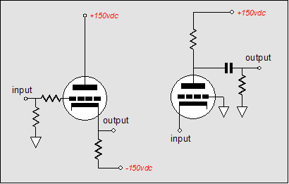
It was fitting that Bronowski, a powerful thinker, was a powerful writer, for as Richard Mitchell pointed out in his book, Less Than Words Can Say, "If we want to pursue extended logical thought, thought that can discover relationships and consequences and devise its own alternatives, we need a discipline imposed from outside of the mind itself. Writing is that discipline. It seems drastic, but we have to suspect that coherent, continuous thought is impossible for those who cannot construct coherent, continuous prose." Okay, back to Rozenblit's book, as I read his following chapter on electricity, I found that he picked up the pace as he went, making it a bit more enjoyable for me, but it left me wondering what the complete novice would think. My guess is that readers would ask the same question that millions of soldiers have asked after painful ten-mile marches: Was this trip really necessary? Rozenblit even covers quantum mechanics and the chemistry of the vacuum tube, I kid you not. When we get to the actual chapter on tube circuits, we find Rozenblit, once again, mislabeling the cathode-coupled amplifier a grounded-grid amplifier. Does he not get the same amount of angry e-mail that I receive? To be more generous to Mr. Rozenblit, the cathode-coupled amplifier is a compound circuit, the wedding of a cathode follower to a grounded-grid amplifier, so his label is half right.
Of course, had he labeled the cathode-coupled amplifier circuit the "cathode follower," he would still be half right but no more helpful. Moreover, this chapter is not all that different from what a Google search would deliver in five minutes. The basic tube circuits are there, with accompanying formulas. He saves the best for the end, where he describes five tube-based projects of his own design:
Alas, this, too, is a mixed bag. The first two projects are most likely to be built; the last three, forgotten. His low-cost OTL is sound enough a design. Of course, I would make several modifications to his circuit, such as adding grid-stopper resistors and a few power-supply enhancements, which I would deem essential improvements; he, fussy and needless embellishments. His second project, a 1W, 300B-based, single-ended, OTL amplifier is surprising. I did not expect such extravagance from him. Four 300B triodes per channel—yet only 1W of output. Impressive, if only as a bold display of a complete want of modesty and economy. If his book held eight more projects like these two, I would have no problem recommending his book. But two interesting projects are simply not enough. Still, the problem remains: I cannot fathom just what was Rozenblit's aim in writing this book or who was his intended audience. The blurb on the book's back cover immodestly states:
Just as learning resource centers were once called libraries, texts were once called books. Thank God for progress. Perhaps you are old enough to remember the TV ads that played late at night for an LP record set of classical music. The sophisticated, British voice over announced that this was all the classical music that you would ever need. Well, this blurb seems to be written by the same marketing agency. Today, with Google just a click away, books must truly deliver something otherwise unattainable. Now that I own this book, I mean text, "the most comprehensive and up to date text on vacuum tube audio currently available," I feel no urge to jettison my extensive collection of electronic books nor cancel my DSL; nor do I really regret buying the book.
So, here is my take on it: if you already own Morgan Jones's excellent books on tube design and amplifier construction, check Rozenblit's book out. If you don't own any Morgan Jones's books, buy them first. On the other hand, if you plan on building one of Rozenblit's circuits, then it seems to me that buying the book that held his circuit is the least that you can do to pay Bruce back.
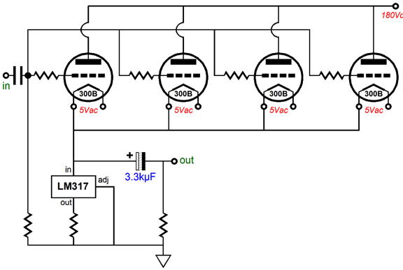
Rozenblit's 300B OTL
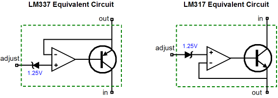
Yes, a constant-current-source-based cathode follower circuit. The idle current is automatically set by the LM317, which is configured as a constant-current source, not a voltage regulator. Each 300B draws a little over 125mA, for a stage total of a little over 500mA. This amount of peak current flow into an 8-ohm load equals 1W, as 0.5² x 8/2 = 1W. Had the idle current been 1A, the 8-ohm load would see 4W. As you might guess, I will offer a modification to this design; one that will quadruple the power output, yet cost only 5 cents more. First, note how the four 300B triodes, working in unison, must swing from 0mA to 1A, so that the load can experience 500mA peaks of current flow. If the speaker could receive the full 1A of current flow through the triodes, however, it would receive 4W of power. In the existing setup, this is not possible, as the constant-current source constantly draws 500mA, which must always be subtracted from the four triode's conduction. So, how do we get the constant-current source work in a push-pull fashion, in opposition to the triodes conduction? Well, I have shown the answer before in blog number 171.
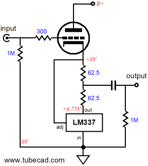
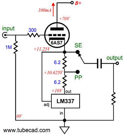
Somersault OTL
At idle, the LM337 functions as a constant-current source, setting a fixed idle current, just as the LM317 had in the original circuit. If the load had attached at the cathode, then the LM337 would perform the exact same job as the LM317, but with the added advantage that the device's TO-220 tab would be at ground potential, which means that it could be fastened directly to the chassis.
But when the Somersault output stage is attached to an external load impedance and music is playing, the LM337 varies its current conduction dynamically, thereby creating a push-pull operation, which effectively doubles the maximum peak current flow into the speaker, which will increase the power output by fourfold. All we need is a toggle switch and we can choose between the two modes of operation: single-ended and push-pull. Both must operate in strict class-A, but the push-pull version does offer four times the power.
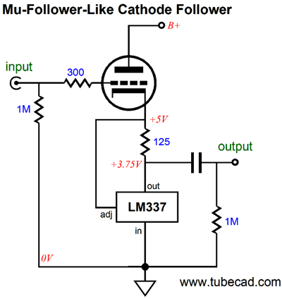
There is a third option, a mu-follower-like configuration.
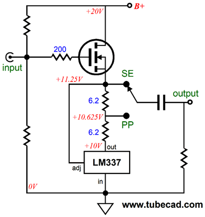
Nor are we restricted to vacuum tubes, as we could replace the triode with MOSFET or transistor.
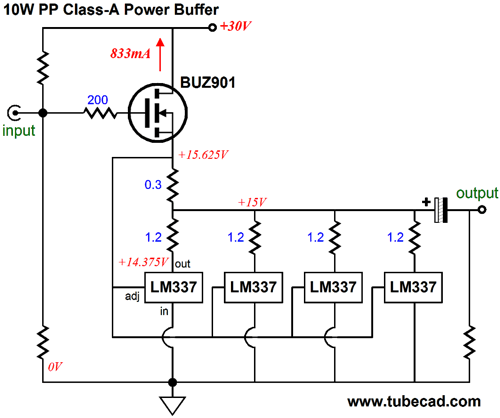
This MOSFET-based Somersault circuit could easily drive low-impedance headphones. Making a version robust enough to drive speakers will take some care, because of its strict class-A operation. For example, getting just 10W into an 8-ohm load will generate a lot of heat at idle and the LM337 is only rated for 15W of dissipation. The workaround is to use four LM337s in parallel.
Note that each LM337 gets its own 1.2-ohm resistor. Why? These four resistors will prevent current hogging, wherein one LM337 might conduct more than its brothers. Before anyone is tempted to ask, yes you could use this circuit with a bipolar power supply, thereby eliminating the need for the coupling capacitor. (I would use a DC servo loop to keep the DC offset low.) By the way, 10w into 8 ohms requires sqrt(10W x 8ohms x 2)V or 12.65Vpk of voltage swing and 1.58A of peak current swing. Thus, the need for an idle current of 833mA and a B+ of about 30Vdc. In blog number 172, I explicate the Somersault circuit further and even show the following schematic. (Yes, it's almost most as if five years ago I anticipated Bruce's 1W OTL and preemptively made a modification to it.) Blog number 174 contains even more information on this topology and is certainly worth reading, if the circuit's operation eludes you. The key feature is that the Somersault circuit is still a class-A affair, although a push-pull circuit. If the triode ever completely shut off, the LM337 will lose its master.
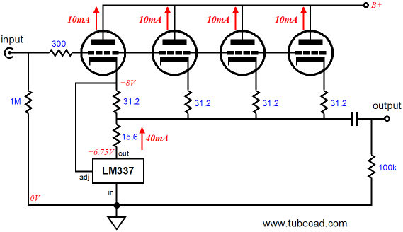
Well, by just doing some simple math to find the new resistors values, we can set the above circuit up to work with four 300B triodes. We end up replacing the 15.6-ohm resistor with 1.2-ohm resistor and all the 31.2-ohm resistors with 4.7-ohm resistors. Now, imagine if your income were increased by fourfold; no doubt, you would be overjoyed. But I am sure that many are not pleased by so paltry an increase in output power, desiring much more power, say 25W or 100W. Well, getting more power is just an IMC away. The 300B-based OTL, whether the single-ended or the push-pull variation, can probably only swing +/-16Vpk, which would limit the maximum power output into 8 ohms to 16W, which is 16 times more than the 1W original after all. If we add the IMC to the Rozenblit single-ended version, then the IMC ratio should be 4:1; to my push-pull version, 2:1.
So, in the first case, R1 = 0.1 ohms, R2 = 0.3 ohms; in the second case, both R1 and R2 equal 0.1 ohms. Wait a minute, I wanted more power and 16W is just not enough. Okay, we can get more power output, but first we will have to make some changes, so the OTL can swing bigger output volts.
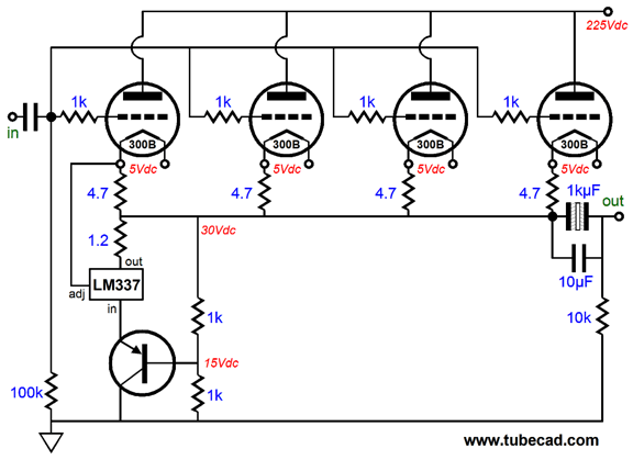
The B+ voltage has been upped to 225V, which allows a bigger cathode-to-grid voltage. Since the LM337 is only rated for 37V or so, we would into that limit far too soon. The workaround is to either use an LM337-HV, which are rare, or cascode the LM337 with a power PNP transistor (or MOSFET). This modification allows much bigger output voltage swings, but it also eliminates the LM337's tab from being at ground potential, so it must be isolated from the chassis. Assuming that this output stage can swing +/-24Vpk, which would create 36W of power into an 8-ohm load, the complementary IMC would need an impedance ratio of 3:1, as 24V/1A = 24 ohms and 24 ohms divided by 8 ohms equals three. Thus, the IMC's R1 value would be 0.1 ohms and R2, 0.2 ohms. Note that the IMC does not bestow a low output impedance independent of the small amplifier that drives it. Do not be fooled by the large, beefy power amplifiers used in its construction. If the small amplifier has an output impedance of 10 ohms, the IMC will relay that 10 ohms and add a wee bit more to it. This may seem to be a failing on the part of the IMC; I regard it as a feature, as it means that the sonic flavor imparted by the small amplifier will get through unimpeded. This means that the above circuit is not enough, that a global negative feedback loop must be put in place, as the raw output impedance will be about 30 ohms. Some readers have wondered why they can't wrap the global negative feedback loop all the way to the speaker's connection, so the IMC falls within the loop. The short answer is that you can. The longer answer is that IMC will have to be part of the design from the beginning, and care will need to exercise to ensure stability. But in theory, the following is certainly possible. How do I know? I have used the circuit below many times, with the small exception that 1-ohm resistor (R2) was actually a 10-ohm resistor.
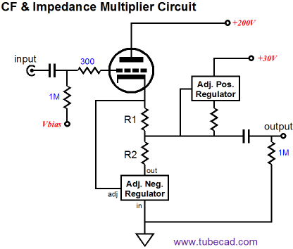
Before leaving this topic, I must show, or rather re-show, this schematic from blog number 174.
This circuit can deliver a lot of current into an external load, yet it is controlled by the triode. It operates in class-A and the positive and negative voltage regulators will dissipate most the heat. Why bother with this circuit? One possibility is building a 300B-basedd hybrid OTL amplifier that sanely only uses one 300B per channel. I have only run SPICE simulations on the above circuit, but the results were encouraging.
Next Time
For those of you who still have old computers running Windows XP (32-bit) or any other Windows 32-bit OS, I have setup the download availability of my old old standards: Tube CAD, SE Amp CAD, and Audio Gadgets. The downloads are at the GlassWare-Yahoo store and the price is only $9.95 for each program. http://glass-ware.stores.yahoo.net/adsoffromgla.html So many have asked that I had to do it. WARNING: THESE THREE PROGRAMS WILL NOT RUN UNDER VISTA 64-Bit or WINDOWS 7 & 8 or any other 64-bit OS. I do plan on remaking all of these programs into 64-bit versions, but it will be a huge ordeal, as programming requires vast chunks of noise-free time, something very rare with children running about. Ideally, I would love to come out with versions that run on iPads and Android-OS tablets.
Next Time
//JRB |
I know that some readers wish to avoid Patreon, so here is a PayPal button instead. Thanks. John Broskie
Kit User Guide PDFs
E-mail from GlassWare Customers
High-quality, double-sided, extra thick, 2-oz traces, plated-through holes, dual sets of resistor pads and pads for two coupling capacitors. Stereo and mono, octal and 9-pin printed circuit boards available.  Aikido PCBs for as little as $24 http://glass-ware.stores.yahoo.net/
Support the Tube CAD Journal & get an extremely powerful push-pull tube-amplifier simulator for TCJ Push-Pull Calculator
TCJ PPC Version 2 Improvements Rebuilt simulation engine *User definable
Download or CD ROM For more information, please visit our Web site : To purchase, please visit our Yahoo Store: |
|||


| www.tubecad.com Copyright © 1999-2014 GlassWare All Rights Reserved |