| John Broskie's Guide to Tube Circuit Analysis & Design |
30 April 2017 Post Number 378 More
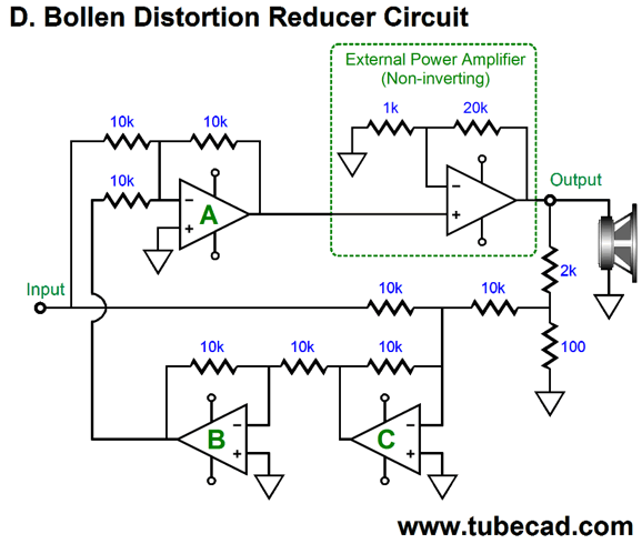
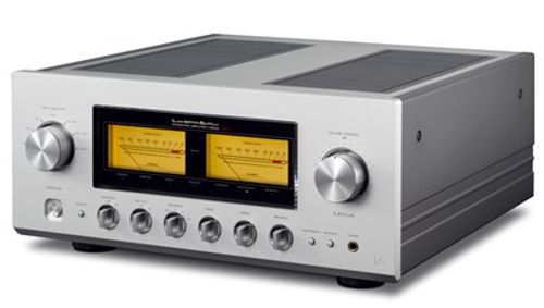
Luxman L-590A I did, however, point out that I often pull off seemingly impossible memory feats, for example I often know where to find sentences in books that I had read 30 years ago. In other words, I often know for certain that the desired quote is to be found on the left-hand page, near the bottom, about 35 pages in. While I search for the text, I don't think anything about my knowing only to look at the bottom of left-hand page; once I find the sentence in the left-hand page, near the bottom, about 35 pages in, I begin to freak, as finding it there was impossible—no one can remember where to find one sentence in a book he has read over 30 years ago. Of course, the relatives didn't believe me. Hell, I didn't believe me. But the next day, while we talked about the supremely great writer, Vladimir Nabokov, I needed to find a great quote from Nabokov's autobiography, Speak Memory. I instantly found the sentence, but then I had re-read this book just a few years ago, not three decades ago.* All memory is a memory feat, if you stop to think about. How very strange that anyone can remember anything. Just because living would prove impossible without does not make memory any less miraculous. After writing post 376, I remembered seeing a schematic for a Luxman power amplifier that used an interesting distortion-reduction scheme similar to the one proposed by D. Bollen in Wireless World, as shown below.
The only problem was that the schematic was stored away safely in a box, a box I hadn't opened once in last seven years. I own about 100 issues of the Japanese magazine, Audio Technology MJ. I distinctly remembered seeing a pertinent schematic in some issue from about 2004 to 2005, in one of the last issues of the year. I also remember the schematic appearing early on in the issue. I dug out 2005, issue 12; nothing there. Issue 11 of 2005, however, held gold on page 8: the review of the Luxman L-590 integrated amplifier, which you can buy for a mere $8,995.
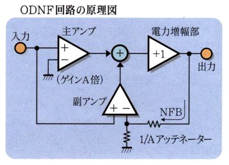
Here is a scan of the conceptual illustration of the Luxman L-590A integrated amplifier from the magazine.
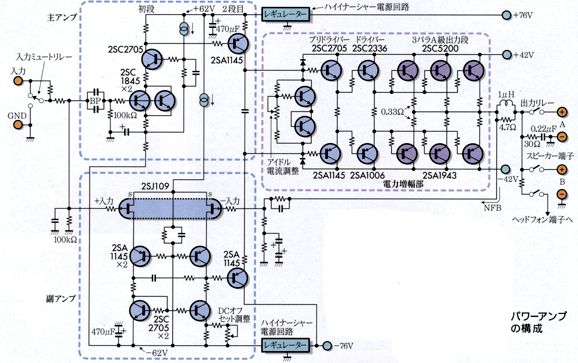
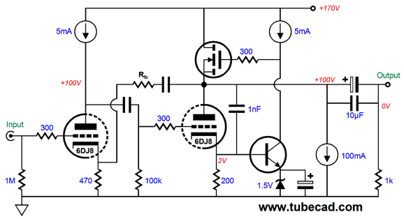
The idea is quite similar to D. Bollen's scheme: a power amplifier's output is attenuated to match the input signal and the difference between these two signals is first inverted and then mixed with the input signal fed to the power amplifier, theoretically resulting in a large reduction in distortion. Here is the actual implementation from the review.
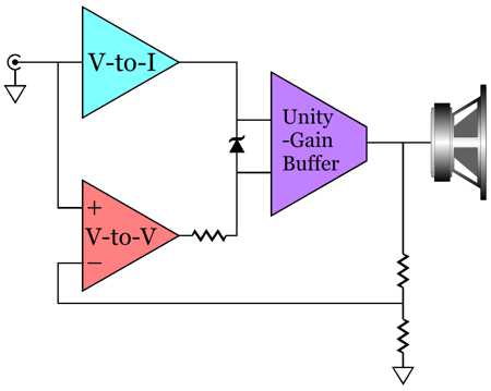
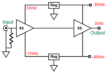
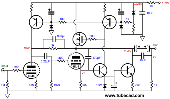
The above schematic holds at least one typo (the PNP transistors in cascode with the input FETs are not biased correctly, as there's a missing resistor to the negative power-supply rail) and no doubt that much is left out; still, there is a lot going on here. (Note the two electrolytic capacitors in series to create a non-polarized capacitor terminating the feedback resistor string. Also note all the base-stopper resistors.) If we look closer—or rather, if we stand back and take a global, comprehensive view—we see that two types of signal amplifiers are used: a voltage-to-current output amplifier (above) and a voltage-to-voltage amplifier (below). Here is the functional diagram.
Where D. Bollen needed three signal amplifiers, this design uses just two. Moreover, all of the Bollen amplifiers were of the voltage-to-voltage type. Because the bottom voltage-to-voltage amplifier holds a resistor in series with its output, the power-supply rail voltage for this amplifier and its brother voltage-to-current amplifier must be higher in voltage than the output stage unity-gain buffer power-supply rails, which indeed they are in the Luxman L-590A, with +/-62V and +/-42V. So, is this approach an actual improvement over the Bollen approach or is it just a way to sidestep existing patents? From day one, the first time I saw Hawksford distortion-reduction scheme (or the Didden scheme or the Bollen scheme or the Luxman scheme), I have thought that all that is going on is that extra negative feedback is being applied, nothing more. For example, the Luxman scheme can be viewed as being no more than this: a fairly conventional solid-state power amplifier, complete with a differential input stage and a fancy signal-modulated constant-current-source loading of the driver stage.
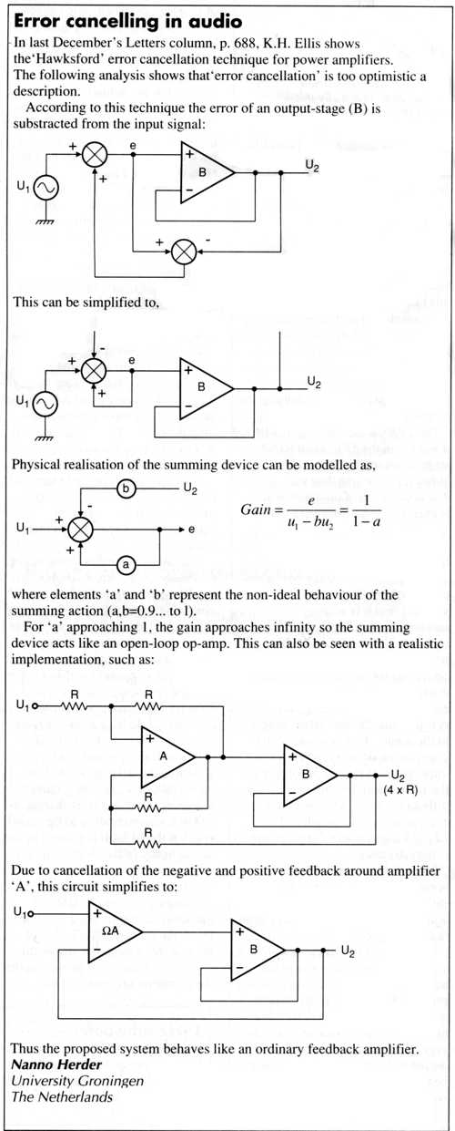
Having mentioned the Hawksford distortion-reduction scheme, I now remember reading in the letter section of Electronics World magazine a reader making this same point. Here is the letter from the April 1997 issue.
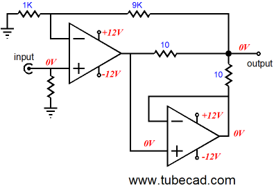
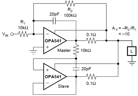
In other words, these various distortion-canceling schemes are really just complex feedback amplifiers. (Feed-forward distortion schemes are altogether different.) Where these various distortion-canceling schemes should be applied, however, is with OpAmps, as we cannot get to the internal circuitry trapped within the IC. This is why I so like the Burr-Brown arrangement of two OpAmps, as shown below.
The top master OpAmp controls the bottom slave OpAmp. Both deliver the same output current into the load, but the top OpAmp is in charge. (See post 261 and post 304 for more details.) In the OPA541 data-sheet, we see how this arrangement can be applied to their power-amplifier OpAmps (as long as the slave amplifier is unity-gain stable, which few chip power amplifiers are).
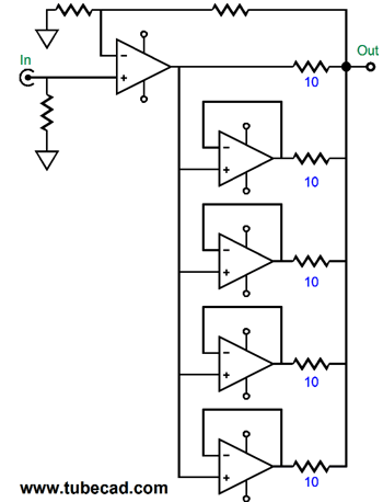
Returning to signal OpAmps, not power amplifiers, we can add more slaves OpAmps, which would allow for more current delivery.
Above, we see one master and four slaves. Assuming a 50mA peak current output from each slave OpAmp, we could get at least 0.2A of peak current flow from this arrangement, which would prove plenty for headphone use. Okay, now think big. What if we used eight or twenty slave OpAmps, such as the LT1364 (50mA) or LT1210 (2A output), we might be able to drive an high-efficiency loudspeaker. One OpAmp to rule them all.
Different Approaches
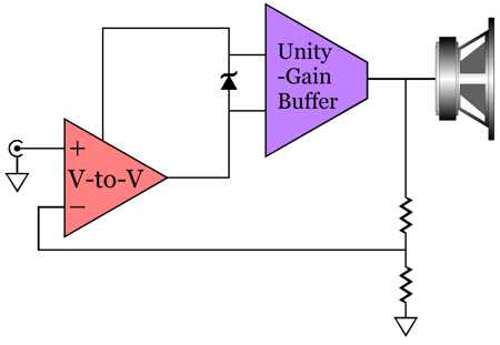
I could not, however, get it to work long term. It would play away nicely for months and then blow its output transistors. I now realize that I needed to put in place a few protection diodes to keep the signal amplifier from overdriving the unity-gain output stage, which it could do easily as its power-supply rail voltages were twice as high as the output stage's. Indeed, as the amplifier was driven hard, the lower power-supply rails would begin to collapse, making the risk the buffer being over driven even greater. I then came up with my two-amplifier solution.
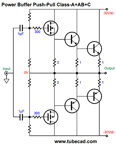
This arrangement proved successful, as I only blew output transistors once, due to shorting speaker cables (I didn't believe in any fuses back then, as I was too much a purist; in fact, I didn't believe in RCA jacks as well, so I directly soldered in place my interconnect cables from preamp to power amplifier). I lifted the compound output stage from a Southwest Technical Products Corporation 215 stereo power amplifier, which was designed by Daniel Meyer. I devised my own input signal applier, which was a fully complementary design. I regulated the rail voltages fed to the input amplifier, which probably bestowed the greatest sonic benefit. Everyone told me that this amplifier produced the sweetest highs they had heard from a solid-state amplifier; the lows were, on the other hand, weak. My big concern at the time was clipping, as I hated it. My goal was a solid-state amplifier that clipped as gently as my tube applier. I believe that since the input amplifier never clipped, it never had to recover from clipping. The output amplifier did clip, but it was a simple two-stage compound amplifier that quickly returned to normal operation. Today, I believe the best arrangement might be a constant-gm, unity-gain, no-global-feedback, output stage driven by a super-hot (i.e. high-gain) tube line stage amplifier. Class-A output stages, whether single-ended or push-pull, are constant-transconductance, constant-gm, designs. Another constant-gm design is my class-A+AB+C effort. See post 332.
The two MOSFETs operate in class-A, push-pull, which means that they never turn off; the transistors in the middle, class-AB, which means that they are both on at idle, but do cut off under use, and the two transistors at the right, class-C, which means that they are turned off at idle, and only turn on when needed. The output impedance is 0.375 ohms at all times, which means that the gm of the output stage is 2.67A/V at all times. Of course, many more bells and whistles can be added, such as a DC servo and an auto-bias circuit. 
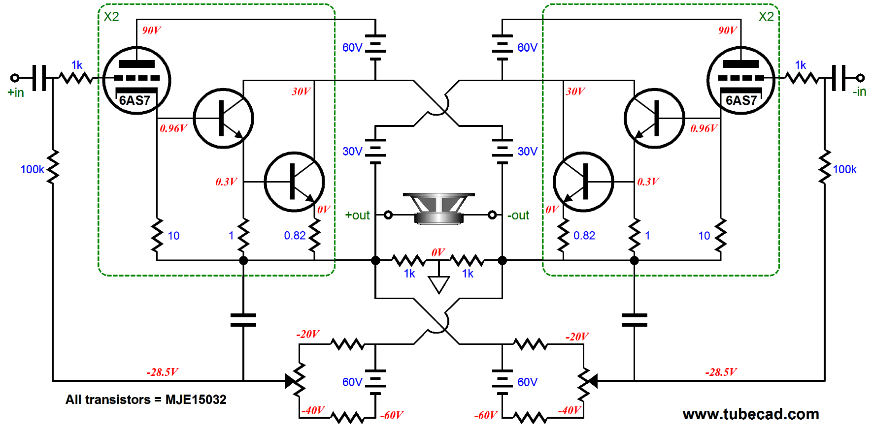
If a balanced input signal is used, then a circlotron setup would prove best.
Note the DC servo on the right and the auto-bias circuit on the left. Nice. Today, I would not use the MJE15032 transistors specified, but the MJL3281A types instead, as they come in the TO−264, case 340G package, which boasts a junction-to-case thermal resistance of only 0.7C/W.
Taming the Triadtron
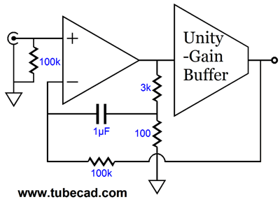
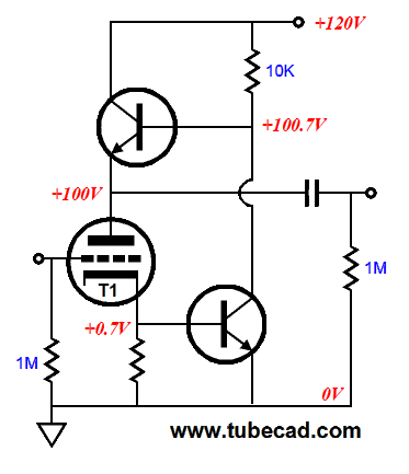
If we cascade a grounded-cathode amplifier with a triadtron, we can apply a negative feedback loop to reduce the gain. The following schematic shows how this is possible.
Yes, I know that it looks as if no negative feedback loop is in place. Nonetheless, it is. See the 3k resistor that bridges the two triode plates; this is a feedback resistor. Remove it and the gain climbs from +13dB to +59dB. Let's rearrange the circuit so the feedback resistor falls into its conventional place.
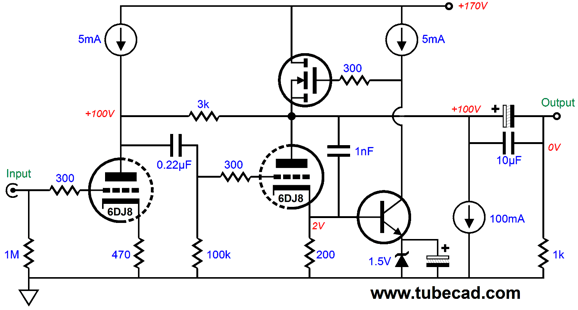
So why not go the conventional way? First, we have an extra capacitor in series with the feedback resistor; Second, good luck making this setup stable. The plate-feedback setup is far easier to get to behave. Why? The conventional feedback setup includes both triodes in the feedback loop, whereas the plate feedback setup only includes the right triode. Thus, in theory, the conventional setup will offer lower distortion, but prove squirrelly in the extreme. Fleshing out the design is simple enough.
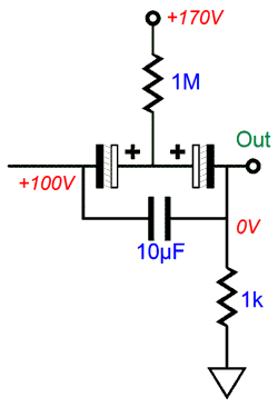
Note the two electrolytic output capacitors, which are placed in series to create a non-polarized electrolytic capacitor. Why not just buy a single non-polarized electrolytic capacitor? As far as I know, no one makes a 200V non-polarized electrolytic capacitor. I do know, however, that there is a lot of controversy over whether it is safe to place two polarized electrolytic capacitors in series to create a non-polarized electrolytic capacitor. I am inclined to think it will work just fine, as the capacitor on the right will see almost all the DC voltage. One workaround that I have seen in a radio schematic is the following.
Each capacitor should be rated for at least 200V. Because the capacitors are in series, the combined capacitance will be halved (assuming equal-valued capacitors). I would use two 470µF/200V capacitors.
Next Time
*Memory and Books Doubly alas, she (and almost everyone else) does not get it: my books are familiar to me, much as your car or house or workplace is familiar to you. The actual physical book I have read does not only hold blotches of ink, it holds my mental map of its contents; a different pressing—or much worse, a digital version—would hold no map. Would you be willing to trade in your old family photos for other peoples family photos, even if the replacements were better photographed or easier to see on your tablet or phone?
//JRB
Patreon
User Guides for GlassWare Software
For those of you who still have old computers running Windows XP (32-bit) or any other Windows 32-bit OS, I have setup the download availability of my old old standards: Tube CAD, SE Amp CAD, and Audio Gadgets. The downloads are at the GlassWare-Yahoo store and the price is only $9.95 for each program. http://glass-ware.stores.yahoo.net/adsoffromgla.html So many have asked that I had to do it. WARNING: THESE THREE PROGRAMS WILL NOT RUN UNDER VISTA 64-Bit or WINDOWS 7 & 8 or any other 64-bit OS. I do plan on remaking all of these programs into 64-bit versions, but it will be a huge ordeal, as programming requires vast chunks of noise-free time, something very rare with children running about. Ideally, I would love to come out with versions that run on iPads and Android-OS tablets. //JRB |
Kit User Guide PDFs
E-mail from GlassWare Customers
High-quality, double-sided, extra thick, 2-oz traces, plated-through holes, dual sets of resistor pads and pads for two coupling capacitors. Stereo and mono, octal and 9-pin printed circuit boards available.
http://glass-ware.stores.yahoo.net/ Support the Tube CAD Journal & get an extremely powerful push-pull tube-amplifier simulator for TCJ Push-Pull Calculator
TCJ PPC Version 2 Improvements Rebuilt simulation engine *User definable
Download or CD ROM For more information, please visit our Web site : To purchase, please visit our Yahoo Store: |
|||


| www.tubecad.com Copyright © 1999-2017 GlassWare All Rights Reserved |