21 April 2021 Post Number 534
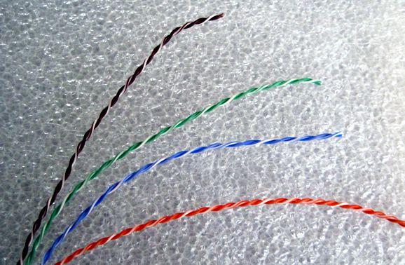
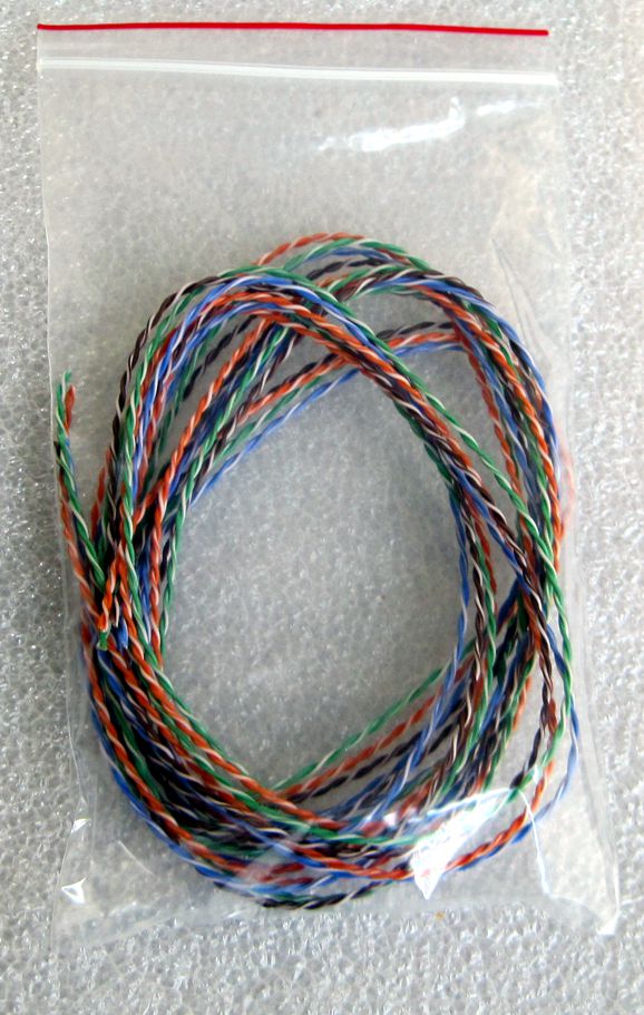
I needed hookup wire, as my old stock finally ran out. I have been making due with taking apart CAT-5 cable, but the results are not ideal. Why not? The wire is either 24 or 26 gauge and the sheathing is usually PVC, which is not very heat resistant, and the wire easily unwinds. I found the solution: 23-gauge, solid-core, Teflon-FEP coated CAT-6 wire. The wire is easy to work with and quite heat resistant (500 °F and 260 °C) and maintains its twist perfectly. I bought more than a lifetimes supply—unless, of course, they find a cure for death. I am selling the excess wire now at my Yahoo-GlassWare store in a package of two meters (79 inches) of four twisted pairs (brown, green, red, and blue). In other words, I did the work of removing the outer jacket.
Here is an example of using the wire in a line-stage amplifier.
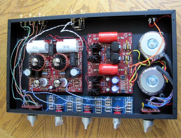
The wire was easy to strip and it held its shape nicely, which made soldering a breeze. The wire is available at the Yahoo-GlassWare store.

Yes, it's back to tube-based moving-coil pre-preamps. I listened to a friend's MC cartridge with 40dB tube-based phono stage of mine. With the line-stage amplifier at full gain, the music played—played amazing well, in fact—but was too noisy. Either a step-up transformer or an active pre-preamp with a 20dB would have made all the difference. Later that day, I filled out two pages in my sketchpad with circuits. My goals were a relatively low B+ voltage of only 100Vdc and only one 6DJ8 tube per channel. It seems to me, unless you are rich or nearing your demise, a pre-preamp that uses a total of six or eight tubes just doesn't make economic sense, in spite of the reduction in noise resulting from so many parallel triodes.
(Perhaps, I am being stupid here. I have known audiophiles who disdain battery-powered gear, as they cannot bear the expense of replacing batteries every two or three months, but who own $5,000 phono cartridges, which they replace after only 1,000 LP playbacks, which works out to $5 per LP played. Eight 6DJ8 tubes might cost $160 and need to be replaced after 2,000 hours of use, which equals about 3,000 LP playbacks or about 5 cents per LP.)
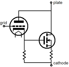
My first circuit was based on the super-triode concept, where the three essential conditions are met. What? Which three? From 2017's post 375:
The Super-Triode concept requires three things:
- Running the triode under constant-current.
- Using beefier devices, either tube or solid-state, to drive entirely—with no help from the triode—the external load impedance
- Letting the triode control the output.
The aim is to superimpose the triode's sonic footprint on the beefier device's output signal. Imagine a single 300B that could put out 200W, which will give you a good idea of what an ideal super-triode amplifier might be like. By the way, post 375 is a fun read and it does a fair job of explicating super-triode operation.
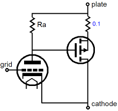
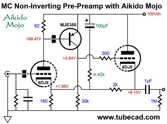
Returning to MC pre-preamps, the following circuit uses a NPN transistor to supercharge the input triode, so the triode's current conduction remains close to constant.
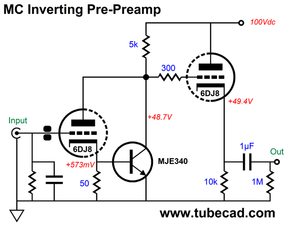
The two black dots at the input triode's grid represent a ferrite bead, which takes the place of a grid-stopper resistor and works to prevent RFI from being amplified. The input triode draws close to 6mA, while the NPN transistor draws 4.5mA. The triode's current variation in the presence of input signal is tiny compared to the transistor's. In other words, the triode draws a nearly constant current, as it sees its plate voltage move in anti-phase to the input signal. If the ratio between the grid voltage swings and plate voltage swings were equal to the amplification factor (mu), then the triode's current conduction would remain truly flat, i.e. constant.
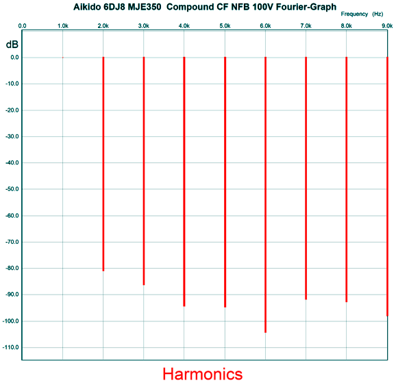
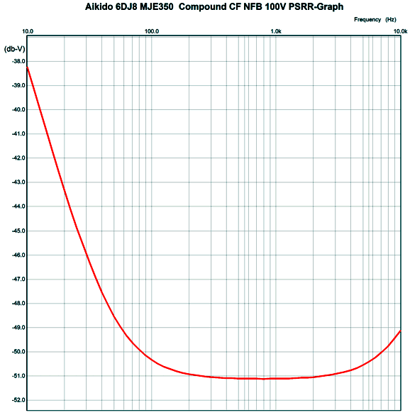
Of course, with a 100-ohm cathode resistor, the triode's cathode cannot exactly trace the exact same signal amplitude that the grid sees; moreover, the transistor transconductance, although very high, is not infinite. The result is that the input triode's gain falls a wee bit below the triode's mu. In addition, the cathode follower output stage imposes its own slight reduction in gain. Nonetheless, this circuit displays a strong super-triode personality. How well does it perform? Here is the SPICE-generated Fourier graph for 27mV of output with an input signal of 1mV. (This is a crazy amount of output for pre-preamp, as 5mV is what we would expect in actual use.)
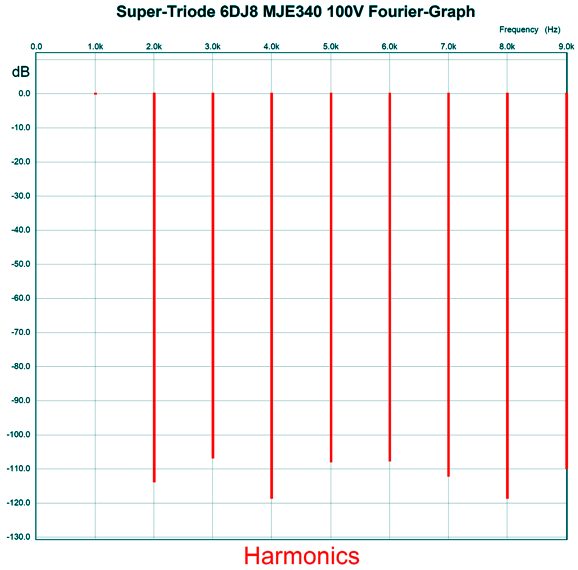
Very low distortion. The PSRR, however, was weak. The answer is Aikido mojo.
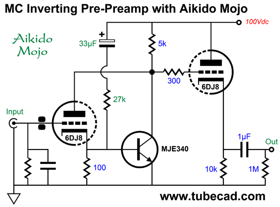
The added capacitor and resistor inject a small sampling of the B+ voltage noise into the transistor's base, which prompts a phase inversion and amplification that its collector, thereby creating a power-supply-noise null at the output. Without the Aikido-mojo enhancement, the PSRR is only -20dB; with it, -56dB.
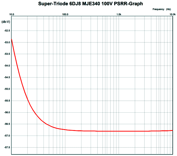
There is no peaking at ultra-high frequencies and the high-frequency bandwidth extends beyond 10MHz. The gain is 28.6dB.
The super-triode topology strives to realize a gain equal to the triode's mu. Thus, to lower or to increase the gain requires using a different triode, which is problem, as most other Hi-Fi twin-triode tubes present more noise due to their weaker transconductance. This would not be quite as important in MM-cartridge phono preamp with a gain of 40dB, but in an MC pre-preamp it is decisive. The usual workaround is to use a negative feedback loop to set the desired gain.
Here is an example that uses two triodes and a PNP transistor.
Much like in the previous circuit, the transistor strives to see a fixed emitter-to-base voltage, which is only possible if the triode conducts a fixed current, i.e. a constant current. The transistor is effectively configured as a common-emitter amplifier and its signal output at its collector is inverted. Since we have two inverting amplifier in series, the signal passed on to the cathode follower is in phase with the signal from the cartridge. Since the cathode follower's output is in phase, we can return it to the input triode's cathode, thereby creating a negative feedback loop.
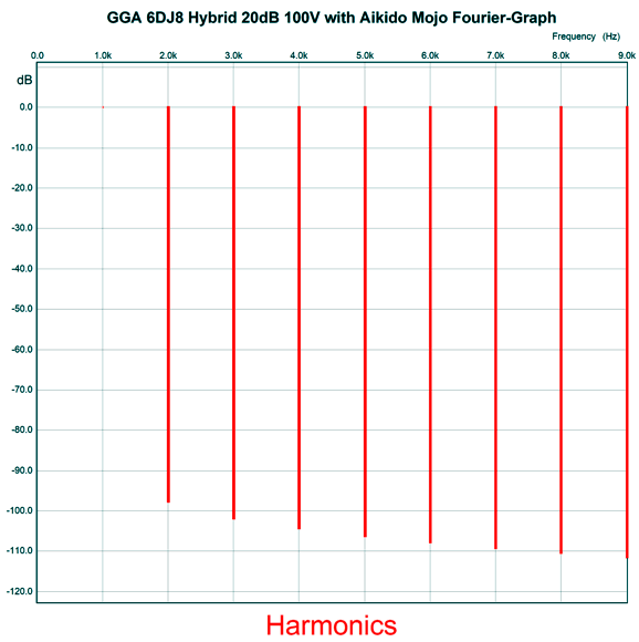
The current flow through the input triode is a heavy 8.6mA, while the cathode follower experiences a modest 3mA of idle current flow. In contrast, the transistor draws a trivial amount of current, only 0.2mA. In other words, no heatsink is required. The distortion is low, as we can see below, but it is not as low as the previous design, in spite of only 10.5mV of peak output not 28mV.
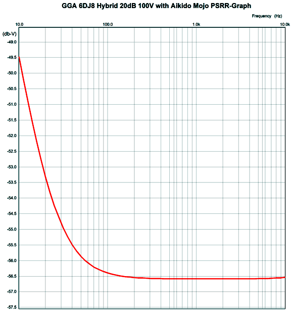
The gain is a tad over 20dB (1:10) and the PSRR at 100Hz is a poor -9dB. The obvious workaround is to include some Aikido mojo.
The added capacitor and resistor bring the PSRR down to -50dB, much better.
An MC pre-preamp should be as quiet as possible, and the inclusion of the Aikido mojo parts moves us in that direction. The circuit's -3dB bandwidth, with a 1µF output coupling capacitor and a 47k load impedance, is 3.3Hz to 6MHz without any peaking.
The next schematic in my sketchpad will confuse many, I fear. It is either a cascode or a variation on the cathode-coupled amplifier.
Compared to the previous circuits, this circuit did not shine, which makes sense as the transistor is doing all the amplification and the input cathode follower develops higher distortion due to the 100-ohm cathode resistor and the transistor's low emitter impedance.
My last circuit sketched was an all-tube cathode-coupled amplifier.
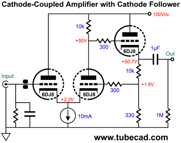
Both triodes experience about 5mA of idle current flow from the 10mA constant-current source. Since the differential triode on the right sees only half the plate voltage, its grid voltage must be higher to compensate for the lower cathode-to-plate voltage. The quick math states that the reduction in plate voltage divided by the triode's amplification factor (mu) should be the require grid DC voltage. SPICE simulations confirmed the math, as 50V/31 equals 1.612V. The gain comes in at 1:11 or +20.8dB and the high-frequency bandwidth extends out to 10MHz with no peaking. The distortion is both low and nicely structured.
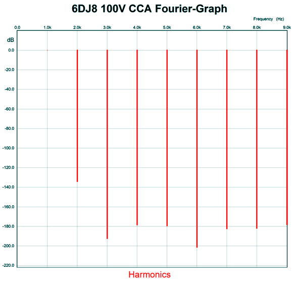
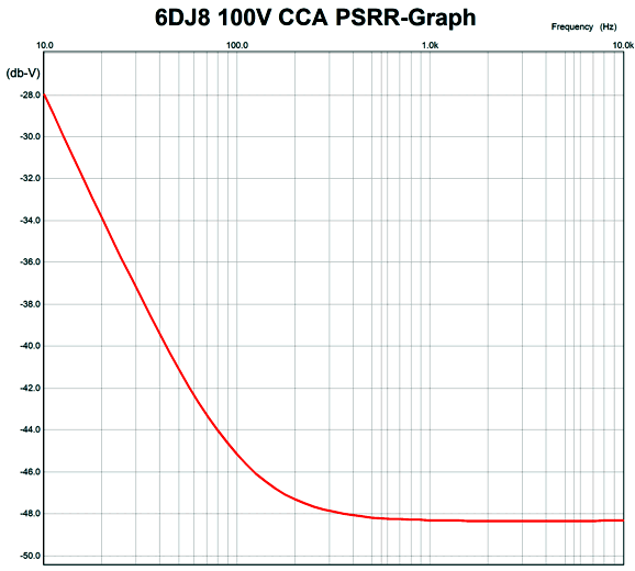
Its PSRR, however, is very weak at only -4dB. As you might expect, we can make a huge improvement by adding some Aikido mojo in the form of the capacitor-resistor addition. (You are noting the pattern, I hope.)
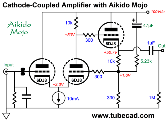
With the added Aikido mojo, the PSRR improve to a reasonable -47dB at 100Hz.
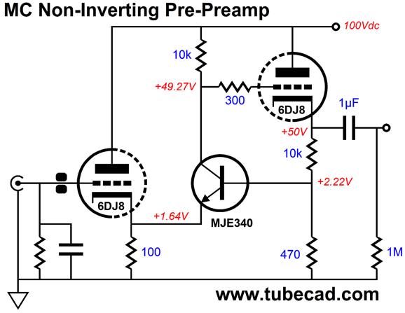
Much better. What I didn't like about this circuit was the need for three triodes per channel. I wondered what an emitter follower would do. In other words, what if we replace the cathode follower with a transistor buffer?
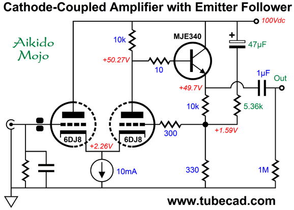
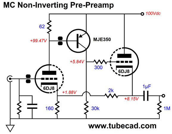
The MJE340 NPN transistor only draws 4.76mA and dissipates only a quarter of a watt of heat, so no heatsink is needed. We get a mixed bag of results, as the distortion rises a bit, but the PSRR improves. Note the 470µF Aikido mojo capacitor and the 5.36k resistor. Such a large valued capacitor was needed to extend the PSRR null down to 100Hz.
We get -64dB at 100Hz, which is impressive.
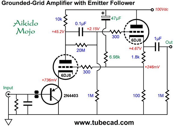
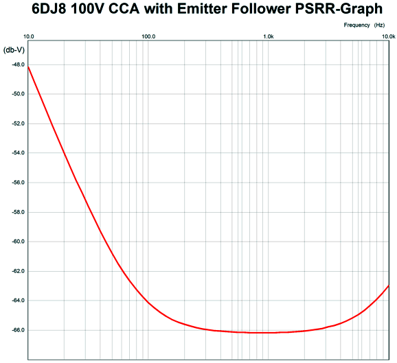
It looks a bit complicated, but in essence it is a grounded-grid amplifier. The input transistor merely buffers the MC cartridge's output and offers a 0.73Vdc voltage shift to the triode's cathode. In SPICE simulations, the distortion was low.
The Aikido-mojo enhancement resulted in a fine PSRR. Here was my last design.
The only thing I worry about is the tiny trickle of base current that must flow through the cartridge coil and its load resistor.

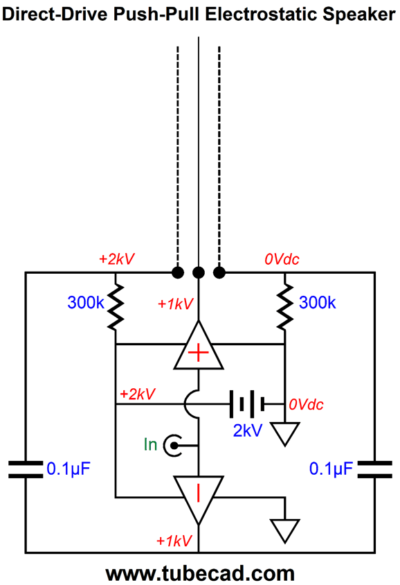
Post 532 mentioned Harold Beveridge's amazing electrostatic loudspeaker design, which is unique in that he drove both the stators and the diaphragm, using two OTL amplifiers. In the overwhelming majority of electrostatic speakers, the diaphragm passively sits between two driven stators, biased to a high-voltage through a many mega-ohm resistor, pushed forward and backward by the developing electrostatic forces. A few electrostatic designs stand this setup o its head, driving the diaphragm, with the stators passively biased to positive and negative high voltages. See post 400 for more information.
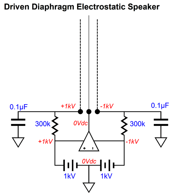
Thus, we have three possible arrangements of a push-pull electrostatic loudspeaker.
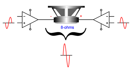
Driving both the stators and the diaphragm effectively doubles the output swing of the OTL amplifiers. Normally, this sort of bridge-amplifier arrangement is the last thing we want to do with an OTL power amplifier, as the tube-based OTL amplifier is severely current limited and bridging effectively halves the loudspeaker resistance. Indeed, if we wanted to get more output power from an OTL amplifier, the best arrangement would be to place two OTL amplifiers in parallel, as the doubled peak current delivery would result in four times the output power. In contrast, solid-state power amplifiers are voltage limited, so bridging makes far more sense, as the doubled voltage swing makes for four times more power output.
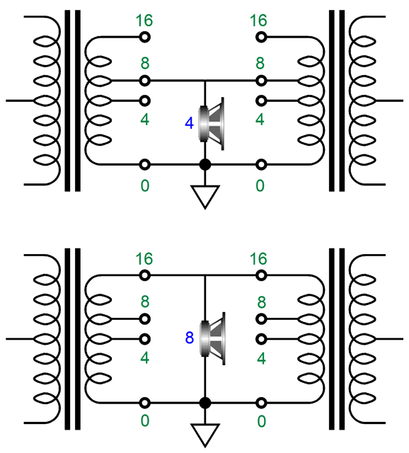
With a tube-based transformer-coupled power amplifier, the amplifier is neither voltage nor current limited, but optimally configured to deliver both voltage and current into a specified load impedance; thus, the 4-ohm, 8-ohm, and 16-ohm output taps on the output transformer. We can create a bridge amplifier out of a stereo tube-based power amplifier, but we will only double the power output, as there is not any wasted potential current or voltage to exploit. With an 8-ohm loudspeaker, we attach it to the two 4-ohm output taps.
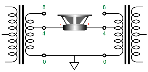
If we own 4-ohm loudspeakers, we are out of luck with this arrangement, unless the output transformers offer 2-ohm output taps. With 4-ohm loudspeakers, the workaround is to place the output transformer secondaries in parallel and attach the 4-ohm loudspeaker across the 8-ohm tap and ground.
One advantage to this setup is that we do not need a unity-gain phase splitter, as both amplifiers receive the same input signal. The disadvantage is that we do not get the benefit of increased PSRR, which previous arrangement delivers, as the loudspeaker would ignore the common-mode power-supply noise.
Okay, returning to electrostatic loudspeakers, the Beveridge arrangement of driving both the stators and the diaphragm not only doubles the effective output voltage swing from the two OTL power amplifiers, it overcomes a problem that few know about. (In this application, the OTL power amplifiers are effectively voltage limited, so the doubling of output voltage swing is welcomed.)
In the conventional electrostatic-loudspeaker arrangement, the diaphragm connects to a super-high-resistance resistor, say, 30M, which in turn attaches to a high-voltage power supply, say, 1kV. The resistor serves two purposes, it limits the peak current flow should the diaphragm slap against a stator and it creates a constant-charge relationship between the diaphragm and stators, which lower distortion. Here is the problem: humidity.
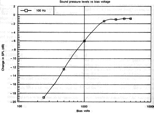
I live in an arid part of the country and I love it, as I hate humidity. Thus, I could never live in Florida. In addition, I would have no problem running electrostatic loudspeakers, whereas those living in Florida might. When the air is dry, its resistance between the diaphragm and the stators might be as high as 270M, so the two-resistor voltage divider formed by the 30M resistor and the air resistance would leave 900Vdc of bias voltage on the diaphragm. On a particularly muggy day in Miami, the air resistance might be a low 30M, so the diaphragm's bias voltage would drop to only 500Vdc, resulting in a drop in SPL. (The exception is when the bias voltage was set far above the polarizing voltage knee, beyond which no further gains in SPL are possible. In this example, the knee voltage was 500Vdc; usually, it is much higher, as shown below.)
In contrast, with the arrangement of driving both the stators and the diaphragm, the bias resistors can be a low 300k, not 30M. Thus, with a drop in air resistance to 30M, the bias voltage would be 980Vdc.
One key difference when we drive the diaphragm is that the diaphragm must present a relatively low DC resistance, not a high one. Capacitors being charged and discharged require current, so we must provide an easy path for the current to flow. Metallized mylar is one possibility.
Switching to another electrostatic-related topic, electrostatic loudspeakers are big capacitors. Capacitors present an infinite impedance at DC and low impedance at high-frequencies; at ultra-high frequencies, a near dead short. Yet, the first thing one thinks of concerning electrostatic loudspeakers is great highs. I believe the optimal loudspeaker would hold electrostatic bass drivers and a ribbon tweeter. Not the usual 8-ohm or 4-ohm ribbon, but a 0.01-ohm ribbon, which would couple to the power amplifier through a step-down transformer. In other words, the electrostatic panel would use a step-up transformer with a winding ratio of 1:28 and the ribbon tweeter a step-down transformer with a winding ratio of 28:1. Thus, the voltage ratio between the two transformer outputs would be 784.
The conventional 100W power amplifier, either tube-based or solid-state, would put out a peak voltage swing of 40V, so the tweeter would see only 1.428Vpk, while the electrostatic panels would see 1,120Vpk swings. The great advantage the ribbon offers is that it is a non-inductive design, so at high-frequencies its impedance is flat. At lower frequencies, the electrostatic panels present a high impedance, so the power amplifier would be largely unloaded, which might complicate the crossover design.
The more I think about it, I believe that the electrostatic panel's capacitance could simply be part of the crossover—if the crossover were the series type. Let's start with conventional dynamic loudspeaker drivers in a two-way system.
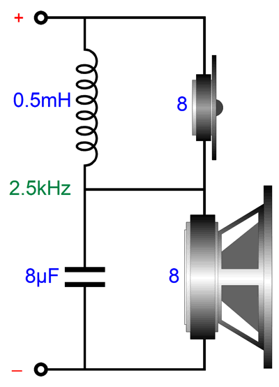
At high-frequencies, the crossover capacitor shunts the woofer and the inductor un-shunts the tweeter. At low-frequencies, the crossover capacitor un-shunts the woofer and the inductor shunts the tweeter. At all frequencies, the current takes the path of least resistance. Now, let's replace the woofer with a large electrostatic panel of high capacitance, say, 10,000pF worth, which is crazy high.
The step-up transformer will reflect the capacitance at its primary, increasing its capacitance by the winding ratio squared. For example, a 10,000pF capacitance would reflect as a 7.84µF capacitor, which against an 8-ohm tweeter equals a crossover frequency of 2,540 Hz. The added 8-ohm power resistor completes the series crossover. Would this work? Perhaps, not as well as I would like, as the electrostatic bass panel would still see big voltage swings at high-frequencies. The workaround might be to use an actual capacitor in the crossover, with the electrostatic panel's capacitance supplementing it, not replacing it altogether. Let's use a more realistic panel capacitance of 3,000pF.
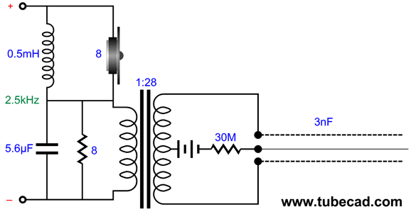
Here is the impedance of a 3,000pF (3nF) capacitor against frequency.
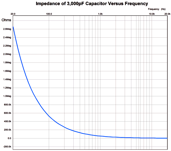
At 20Hz, the impedance is over 2.6M, but at 20kHz it falls to 2,650 ohms. This is not the impedance that the power amplifier will have to drive, as we must include the step-up transformer. With a a winding ratio of 1:28, the impedance ratio equals 28² or 1:784. In other words, we must divide the impedance by 784.
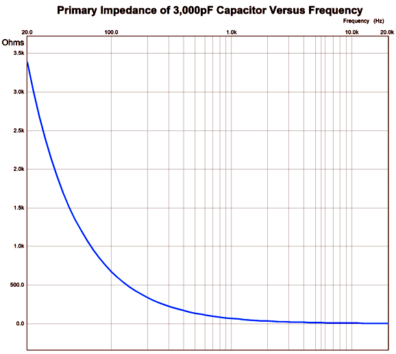
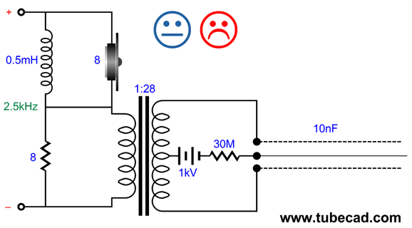
Now, at 20kHz the load impedance falls to 5.975 ohms. Now let's replace the dome tweeter with a ribbon and its step-down transformer.
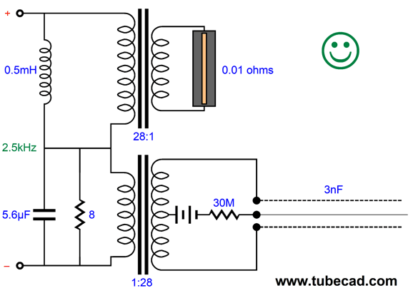
The large-valued capacitor shunts the step-up transformer's primary, so its secondary cannot experience the big voltage swings at high-frequencies. The resistor loads the amplifier at low frequencies, as the electrostatic panel's impedance is very high at those frequencies. At DC, the two transformer DCRs in series make up the load resistance. This potentially low resistance makes DC offsets from the power amplifier particularly dangerous.
Long ago, Mark Levinson stacked two Quad electrostatic loudspeakers vertically, with a Decca ribbon tweeter in between. His HQD loudspeakers were augmented by active 24-inch subwoofers. I heard the speakers once and I was stunned by the great sound. Today, I would love to hear a tall hybrid loudspeaker with a five-foot long vertical ribbon tweeter next to an electrostatic midrange panel and a larger electrostatic bass panel (augmented by active subwoofers). Think Magnepan 20.7 speakers with electrostatic panels.

The complaint I imagine that many will make is that the two transformers are the weak links, the very weak links. Is this so? Starting with the electrostatic step-up transformer, if you followed my last post's recommendation that you check out Jazzman's DIY Electrostatic Loudspeaker Page, you will notice that Jazzman uses two 50VA 230V/two-6V toroidal transformers run backwards to step up the voltage leaving the power amplifier; these are power supply transformers, not tube audio output transformers. Long ago, I made many test of such toroid transformers and I was surprised by well they worked as audio transformers, at least with low frequencies, say up to 6kHz. Today, the performance might be greatly improved due to improved production techniques. Well, if we limited the electrostatic panel to 2,500Hz, then the toroidal power supply transformers would have a greatly truncated bandwidth to cover.
What about the step-down transformer for the long ribbon tweeter? The ideal situation for an audio transformer is a dead short for a load, just the opposite of what most pleases an output coupling capacitor. A ribbon with a DCR of only 0.01 ohms comes close to being a dead short, so very little inductance is needed. In fact, less than 1µH of inductance is needed to ensure bandwidth down to 2,500Hz with a 0.01-ohm load resistance. Not Henries, but micro Henries. Indeed, even with an 8-ohm load, only 0.5mH is needed.
In other words, the step-down transformer may not need a core other than air. (I would look into using a tapped inductor, i.e. an autoformer.) By the way, with a winding ratio of 28:1, the 100W power amplifier's peak output voltage of 40Vpk would appear as 1.43Vpk at the secondary; its 5Apk of peak current swing would increase to 140Apk. In other words, we would get a lot of SPL from the ribbon tweeter, as it is current flow within a magnetic field that creates movement.
One problem often encountered with driving electrostatic speakers is that the power amplifier will either blow a fuse or go into self-protection mode when connected to a capacitive load at turn-on. The workaround is to either turn on the amplifier first and then connect the ES speakers or to use a relay on the amplifier's output or to place a 1-ohm resistor in series with the ES speaker. I believe the hybrid speaker I am proposing here would side step this problem, as the speaker impedance at high frequencies would be 8 ohms.
Recently, I was looking through Frederick V. Hunt's book, Electroacoustics, and I was tickled by the following paragraph:
The fundamental nature of electrostatic forces is direct mechanical action exerted on relatively imponderable electric charges. In this respect these forces contrast sharply with the body stresses that characterize piezoelectricity and magnetostriction, and with the magnetic and electromagnetic forces that act on massive conductors of magnetic flux or electric current. The relatively small magnitude of electrostatic forces, and the ease with which their action can be brought to bear uniformly over extended areas, marks this mechanism of transduction as one of inherently low internal impedance — a force generator of high internal mobility, to put it in terms of the "other" analogy. But since the acoustic impedance of air is likewise low, it follows that there should be an essential "Rightness" about the employment of electrostatic mechanisms for the transduction of airborne sounds.
page 168

Italians Ferruccio Spinetti (bass) and Giovanni Ceccarelli (piano) and Belgian singer Chrystel Wautier pay tribute to the memory of the late Italian composer and conductor Ennio Morricone (1928 - 2020). Double bassist Ferruccio Spietti is half of the duo Musica Nuda with Petra Magoni. I had nothing but praise for Musica Nuda in post 448. I sporadically check for any new albums from them, which is how I discovered this album.
More Morricone is well recorded and makes a fine listening experience. I would classify the album as Italian jazz. Defintely worth a listen.
//JRB
Did you get your money's worth with this post by me? If so, think about supporting me at Patreon.

  
Just click on any of the above images to download a PDF of the user guides.

For those of you who still have old computers running Windows XP (32-bit) or any other Windows 32-bit OS, I have setup the download availability of my old old standards: Tube CAD, SE Amp CAD, and Audio Gadgets. The downloads are at the GlassWare-Yahoo store and the price is only $9.95 for each program.
http://glass-ware.stores.yahoo.net/adsoffromgla.html
So many have asked that I had to do it.
WARNING: THESE THREE PROGRAMS WILL NOT RUN UNDER VISTA 64-Bit or WINDOWS 7, 8, and 10 if the OS is not 32-bit or if the OS is 64-bit.
I do plan on remaking all of these programs into 64-bit versions, but it will be a huge ordeal, as programming requires vast chunks of noise-free time, something very rare with children running about. Ideally, I would love to come out with versions that run on iPads and Android-OS tablets.
|


