| John Broskie's Guide to Tube Circuit Analysis & Design |
| Post 213 01 September 2011
More B & B Cathode Follower Circuits
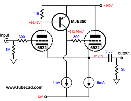
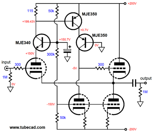
"Theme" is the right word, as a unifying or dominant idea, motif, configuration, structure is what I want to highlight. For example, the following circuit may not at first look anything like the B & B CF shown in Blog No. 212, but its essence is identical.
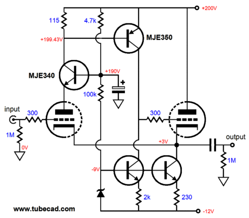
It looks quite different from the simple B & B cathode follower in terms of parts used. But if we look into the functions performed, not the parts used, the same B & B cathode follower is evident. In other words, the same single PNP transistor and two top triodes are key, the rest is just support circuitry. The same holds true for this variation on the B & B cathode follower theme.
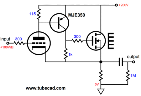
The two triodes and the PNP transistor define the key structural feature. Moreover, these devices are not restricted to certain triodes and only one type of transistor, as a 211 and 845 transmitting tubes could be used, as could a hundred other high-voltage PNP transistors. In fact, I would argue that the following also belong to the family of B & B cathode follower, although only one triode is used.
The three essential roles are being filled, albeit with the MOSFET taking the second triode's role. The triode accepts the input signal and compares it to what appears at its cathode. Any discrepancy results in a variation in the triode's conduction of current, which the PNP transistor is loathed to see, as I strives to maintain a constant current conduction through the tube, so it reacts which prompts the MOSFET into action, bringing the output back in line with the input. The next circuit seems to violate the rules, as the output is taken at the other end, at the plate, not the cathode; indeed, the cathode is locked in place (in AC terms) by the large bypass capacitor, so the cathode could never be forced to follow the input signal.
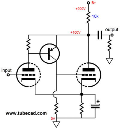
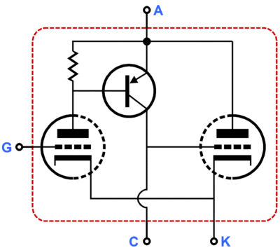
Absolutely, no argument. It doesn't look like the B & B CF, but, nonetheless, I maintain that it is essentially much more like the the B & B CF than not like it. How so? The PNP transistor still is in charge of maintaining a fixed current flow through the left triode. Within the standard B & B CF topology, the variations in current flow through the right triode force the two coupled cathodes in line, thereby ensuring a steady current flow through the input tube. In this circuit, the same principle obtains, but this time it is the plate resistor that experiences the varied current flow, which develops a varying output voltage, which both triodes experience equally. Yet, the goal remains the same: a fixed current flow through the left triode, the input tube of this amplifier. But unlike the B & B CF, this B & B grounded amplifier circuit develops gain. Why the difference? Why do get gain with this circuit, but unity-gain output for the B & B cathode follower? The answer lies in a review of how a triode works. A triode's grid is mu (amplification factor) times more more effective than the triode's plate in controlling current flow through the triode. Thus, if a triode's mu is 10, as in the 6BX7, a 1V pulse applied the to plate will result in only one tenth the current flow change that the same pulse would produce had it been applied to the grid instead. The cathode, on the other hand, is (mu + 1)/mu times more efficient than the grid in controlling current flow. And since in the above circuit, the circuit voltage that varies in response to an AC input signal is the plate, the plate must swing mu times more in the opposite direction from the grid's movement to keep the left triode conducting a fixed current. In other words, if the grid made 1V more positive, the the plate must be made mu times less positive to keep a constant current flow through the triode. In both this grounded-cathode amplifier and the B & B cathode follower configuration, the input grid is equally able to control the current flow through the circuit. Thus, although we seem to have two radically different circuits, the essential inner workings are the same, which is why I want to extract from these circuits this core building block: the quatrode 2.
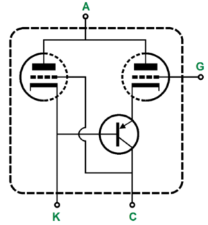
Like the first quatrode and A. J. van Doorn's octode, this scheme defines a basic building block, which finds application in many different, wildly different, applications.
With these schemes, these prepackaged clusters of parts, we can build voltage regulators, single and push-pull amplifiers, buffers... Although not exactly plug-'n-play, using these modular topologies is not that difficult, once the basic functioning is understood. Without this understanding, however, you will be stuck in the dark, fiddling part values in a desperate attempt to luck into a well working circuit.
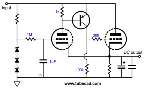
Quatrode-2 Series Voltage Regulator
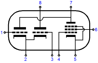
This high-voltage regulator uses the right triode as the pass device in the series regulator, while the left triode compares the output voltage to the fixed DC voltage it sees at its grid. Add once again, the PNP transistor will do its best to keep a constant current flow through the left triode. If small output currents are expected, a 12DW7 could be used, with its internal 12AU7 triode in the right position. Or, if high current demands are expected, then a 6AS7 or 6C33 or triode connected KT88 could be used as the pass device, with a low-noise, high -gm triode used as the input tube. If the left triode is the input tube, what is it signal source? A voltage regulator can be viewed as being a unity-gain amplifier whose input signal is ground, which just happens to exhibit a huge DC offset.
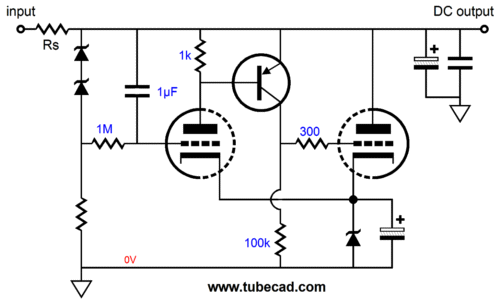
Quatrode-2 Shunt Voltage Regulator
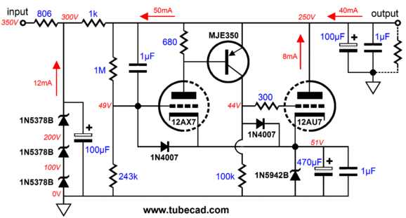
Note the zener that replaced the shared cathode resistor. This zener, along with the other two, are internal voltage references that the shunt regulator uses to calibrate its output voltage. Additionally, this zener establishes a voltage window for the 100k resistor to operate within. Also note the RC filter that scrubs away the zener string's noise, yet freely passes its fixed DC voltage reference. Of course, the zener string that attaches to the output is not essential, as it could be replaced with a resistor. The zeners offer greater DC feedback than a two-resistor voltage divider would, but we seldom require such added DC stability, as we are far more concerned with the regulator's AC performance. In fact, a zener string (made up from a 1N5948B & a 1N5950B zeners) will need to draw about 4mA for the zeners to break at their re fence voltage. The two big problems all shunt regulators that strive to maintain a fixed DC output voltage are: not being loaded and, second, too large a variation in the input voltage. When the external load is removed, the shunting tube must draw all the missing current along with its own nominal idle current. When the raw input DC voltage increases by just 10%, say from 300Vdc to 330Vdc, the shunting tube must dissipate far more than just 10% more heat, possibly 100% or even more. What happens if our shunt regulator encounter these two problems at once, which quite easily could happen, as an unloaded high-voltage, power transformer can easily put out a 10% higher secondary voltage? In fact, 10% more would be quite good, as typical regulation figures for high-voltage power transformers are closer to 20% to 30%, because of the high-DCR of the thin wire used in the secondary. The circuit below shows a fleshed-out Quatrode-2-based tube shunt regulator that strives to cover both possible problems.
Note the three-zener string at the left; its purpose is to pre-shunt regulate the input voltage to 300Vdc; thus eliminating the problem of an over-voltage at the input. The two added 1N4007 rectifiers help with the problem of the regulator being unloaded. THe key word in the last sentence was "help." The problem is not entirely eliminated, as the 12AU7 triode cannot draw 50mA. Instead, the rightmost diode saves the 12AU7 from ever seeing more than +0.7V at its grid (relative to its cathode). The leftmost diode protects the 12AX7 triode at start up from seeing a huge positive voltage at its grid. The assumption behind this shunt regulator has ben that a 12DW7/ECC832 would be used. If it were not used and other tube were used, such as the 6N1P and the EL86 or EL84, then the regulator could maintain a fixed DC output voltage with no external load. (Why the 6N1P as the input triode? Noise. The 6N1P can be fantastically quiet. Why the EL86 or EL84? I love these little guys, as they are tough and offer a good amount of transconductance.) Of course, hundreds of different tubes could be used, such a 300B as the shunt tube (which would make use of the 5Vac winding that goes unused when solid-state rectifiers are used).
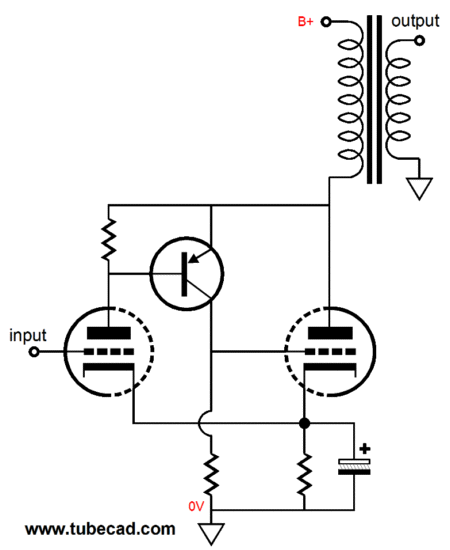
Quatrode-2 Single-Ended Amplifier
This amplifier functions in the same way that the quatrode-2 based grounded-cathode amplifier functions. But many essential parts have been stripped away, in the interest of clarity of purpose. If nothing else, both triodes must be paired up with grid-stopper resistors. In addition, as it is unlikely that a PNP transistor could be found that is capable of withstanding any more than 400V, two or three PNP transistors would have to be placed in cascode. Moreover, the input triode must see the cathode-to-plate voltage swings that the output triode experiences, which is problematic, as the typical triodes we would want to use, such as the 6DJ8, 6SN7, 12BH7, 5687, ECC99 cannot withstand such high-voltage swings; with a 400Vdc B+ voltage, the input triode might see +700V peak voltages. The workaround, in this case, is either use a lower B+ voltage or or use a 12B4 or cascode the input triode, with either another triode or a solid-state device, such as a high-voltage N-channel MOSFET or NPN transistor.
Next Time
//JRB |
|
I know that some readers wish to avoid Patreon, so here is a PayPal button instead. Thanks.
John Broskie
E-mail from GlassWare customers:
And
High-quality, double-sided, extra thick, 2-oz traces, plated-through holes, dual sets of resistor pads and pads for two coupling capacitors. Stereo and mono, octal and 9-pin printed circuit boards available. Aikido PCBs for as little as $20.40 http://glass-ware.stores.yahoo.net/ Only $12.95 TCJ My-Stock DB
Version 2 Improvements *User definable Download or CD ROM www.glass-ware.com |
||
| www.tubecad.com Copyright © 1999-2011 GlassWare All Rights Reserved |
