| John Broskie's Guide to Tube Circuit Analysis & Design |
| October 16 2026 | Post Number 648 |
||||
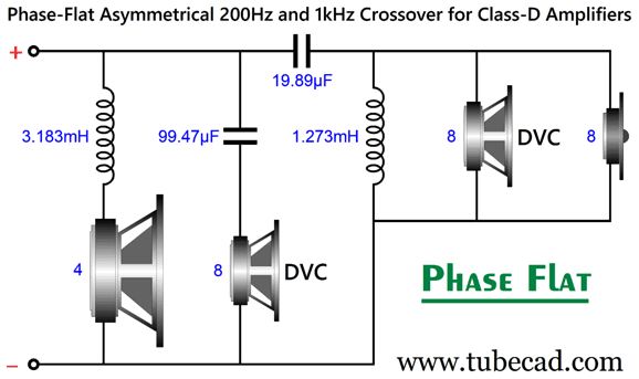
My Latest Ideas What happened recently is that a single novel seed idea, in this case the idea planted last March with my Post 635, namely that the class-D amplifier offers still further possible exploitation, sprouted too many new shoots, too many varied applications. Back in Post 635, the new observation was that, since class-D power amplifiers thrive with low-impedance loads, we can use my novel passive three-way phase-flat speaker crossover that uses just four reactive parts (i.e. two capacitors and two inductors) along with a DVC mid-woofer.
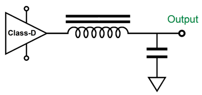
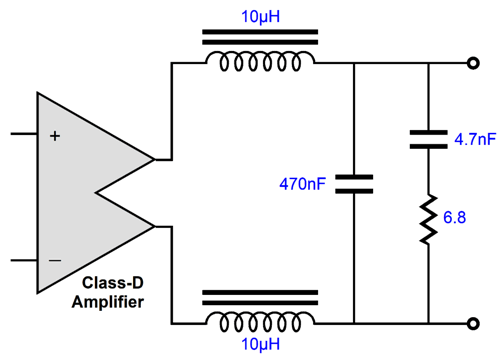
Amazingly enough, the tweeter sees a 2nd-order high-pass filter in this design yet the combined output is transient-perfect. The price we paid was a non-flat load impedance: 4 ohms at low frequencies, 6.6 ohms in the midrange, and 2.66 ohms at high frequencies. This load would make many a class-A and Class-AB power amplifiers unhappy. Not the class-D amplifier, as it already works into a capacitive load at high frequencies, which at ultra-high frequencies approaches zero ohms. Here is the quick class-D amplifier example:
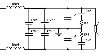
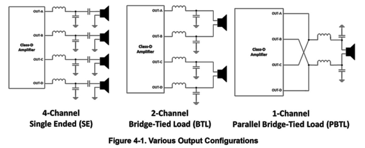
The inductor is often only a trivial 10µH in value, but the capacitor is usually around a big 1µF in value. For example, the popular and acclaimed Texas Instruments class-D amplifier, the TPA3255, a PurePath™ Ultra-HD power amplifier with an analog-input, offers the following recommend output termination for its mono PBTL (Parallel Bridge-Tied Load) mode configuration:
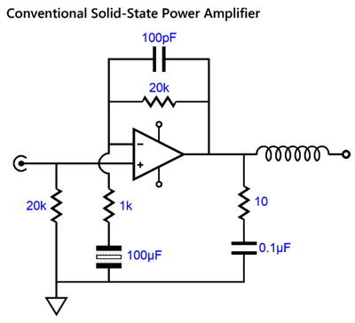
Note that the two 470nF capacitors in parallel equal 0.94µF of capacitance. Many class-A and class-AB solid-state power amplifiers would balk at such a load capacitance. Do you remember back in the late 1970s, when a certain high-end speaker cable presented so much capacitance that amplifiers blew fuses? I do. To prevent this problem the typical class-AB solid-state power amplifiers use the following decoupling network, with the exception that the inductor is usually wrapped around a parallel 10-ohm resistor, which damps the inductor:
Okay, returning to the class-D output configuration, why bother with the ground termination of the capacitors and Zobel networks? In other words, why not use the following low-pass filter instead, thereby saving us the need for extra parts?
Answer: a class-D output stage runs duration-modulated square waves at 400kHz to 800kHz, which the 2nd-order low-pass filter erases, creating a smooth analog output signal. Think of it being like digital running at a crazy-high sampling rate. While this alternate setup does an equally good job of filtering away the high-frequency spuria from affecting the loudspeaker, it fails at the job of not radiating RFI outside the enclosure, as the common-mode spuria travels equally and in phase down the speaker cables; hence, the ground termination. Is this a problem? It might be if you have sensitive electronic equipment nearby. Okay, what if this class-D amplifier resided in the loudspeaker cabinet, with short leads of hookup wire? Maybe, we can worry less.
Class-D and Electrostatic loudspeakers
Electrostatic loudspeakers usually hold step-up audio transformers to turn the low-voltage output from our power amplifiers into high-voltage at the stators. The transformer also magnifies the electrostatic load capacitance by the winding ratio squared. With a winding ratio of 1:30, that's 900 times greater capacitance at the primary, so a 1nF electrostatic panel reflects to the primary as a 0.9µF capacitance. Well, as the class-D amplifier both likes and expects a capacitive load, driving electrostatic loudspeaker with a class-D amplifier makes a lot of sense. In fact, we could probably lose the two inductors, as the step-up transformer exhibits enough leakage inductance to make up for their omission. Hell, why not design an electrostatic-worthy class-D amplifier based on output tubes and a crazy-high-voltage power supply? And, no, David Berning's patented ZOTL topology is not strictly speaking a class-D amplifier, although it shares many of its characteristics. A true class-D amplifier based on high-voltage output tubes would not need an output transformer, as it would only require two series inductors, while the electrostatic panel serves as the needed smoothing capacitor. Of course, high-voltage MOSFETs could be used instead of the tubes.
Class-D and Nelson Pass
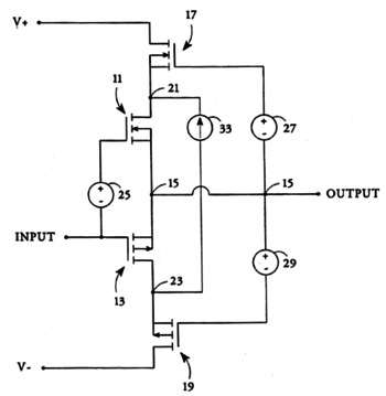
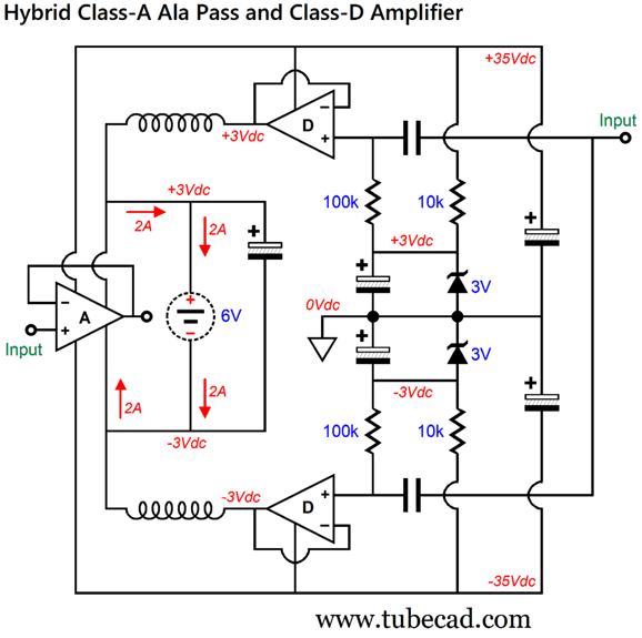
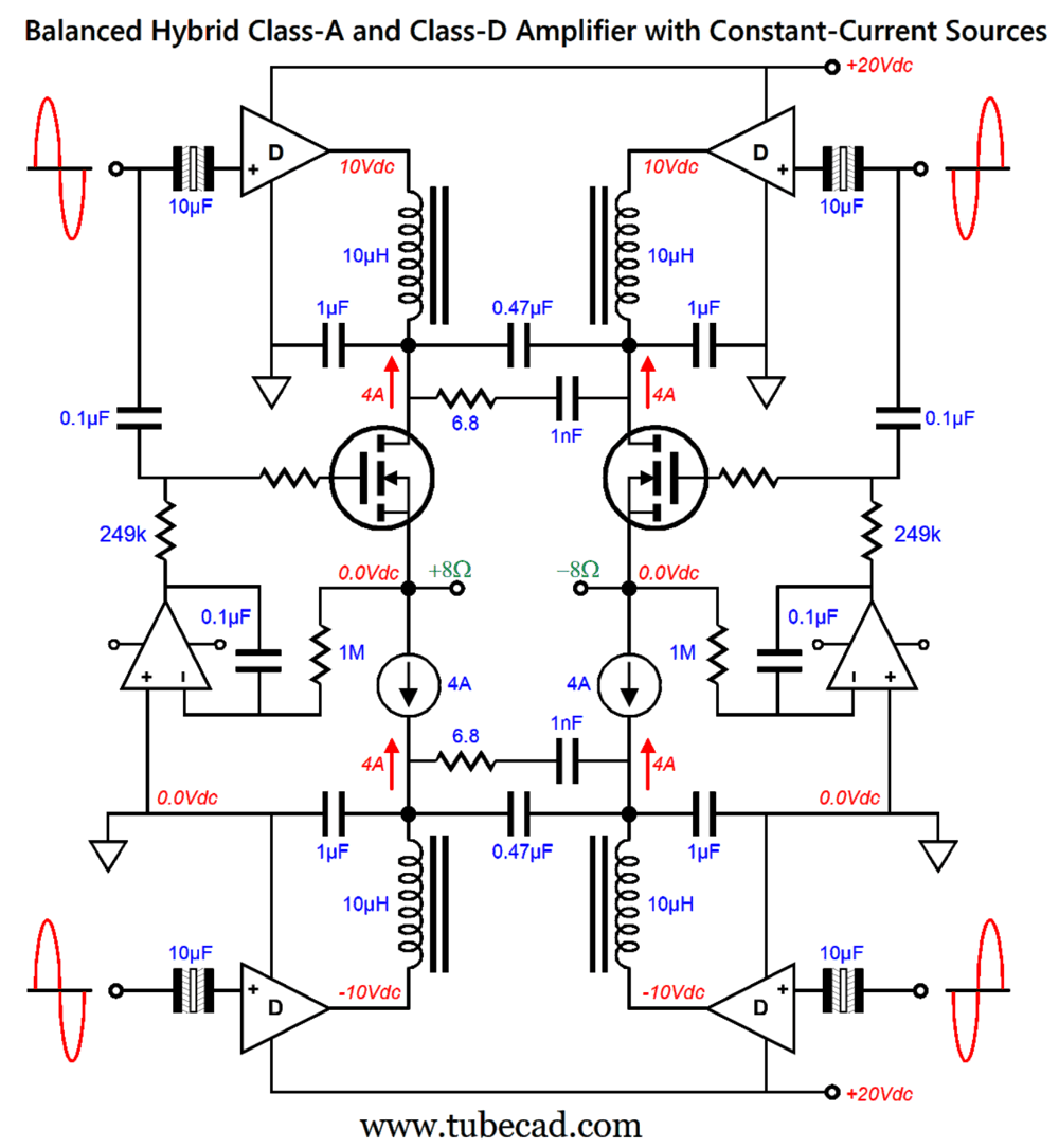
The constant-current source (item 33) includes a floating low-voltage, high-current power supply. The center MOSFETs draw class-A idle current, say 3A, while the top and bottom MOSFETs draw only 100mA. This arrangement delivers class-A purity at class-AB dissipation, as the cascode MOSFETs move the output stage and floating power supply up and down with the output signal. We can replace the top and bottom MOSFETs with two class-D amplifiers, working in-phase and seeing the same input signal as the class-A output stage.
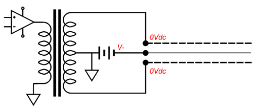
The class-D amplifiers must work with a bipolar power supply and must allow for a fixed DC offset, which means that monopolar class-D amplifier IC amplifiers, such as the TPA3255, cannot be used. The 6V floating power supply can be a switch-mode power supply. The class-A output stage will dissipate 12W at idle, but deliver 60W into an 8-ohm load without leaving the class-A-window of current conduction. Yes, we get to retain our cake and devoir it at the same time. It's much like socialism, except that it actually works. This then led me to think about replacing the class-D amplifiers with variable switch-mode voltage buck regulators, whose output voltage would follow the input signal. But such a variable buck voltage regulator would take some effort to allow for audio-bandwidth tracking. In other words, best to stick to preexisting class-D amplifier designs.
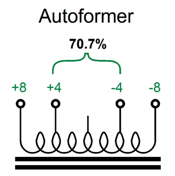
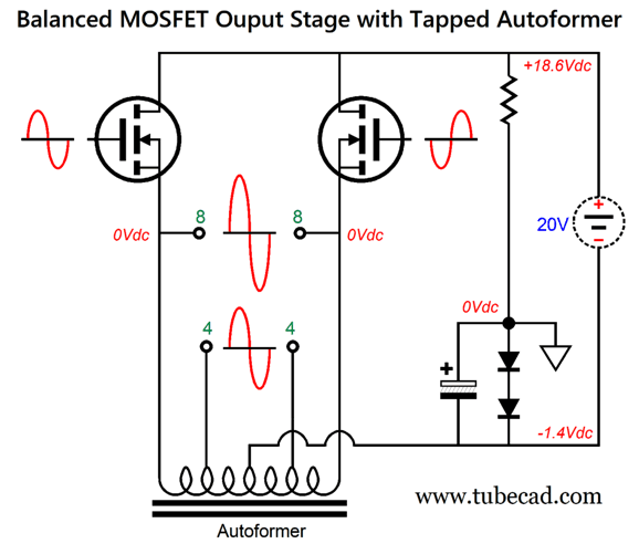
Surprisingly enough, one thing I love about tube-based power amplifiers is their audio output transformers that offer multiple output impedance taps, often 4, 8, and 16 ohms. This allows a class-A amplifier to remain class-A with either a 4 or 8-ohm loudspeaker, something a direct-coupled power amplifier cannot do without increasing the idle current by 1.414 times for 4-ohm loads. An unexploited workaround, however, is the autoformer.
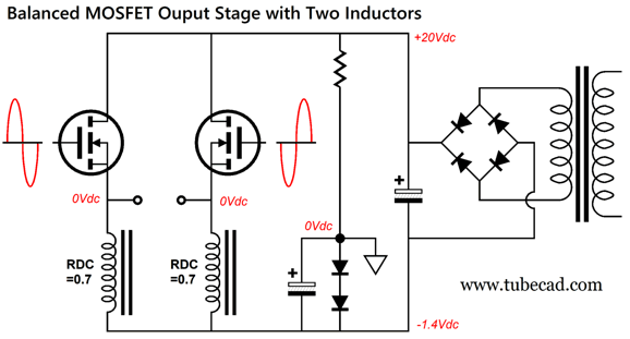
This autoformer assumes a balanced output. A 4-ohm loudspeaker requires 70.7% less voltage swing and 141.4% more current swing than the 8-ohm loudspeaker does to receive the same power delivery. This autoformer performs the conversions for us. In addition, the autoformer allows us to halve the B+ voltage, but at the cost of doubling the idle current. You cannot cheat the math. To get a taste of inductive loading, let's start with a balanced output stage that uses two inductors instead.
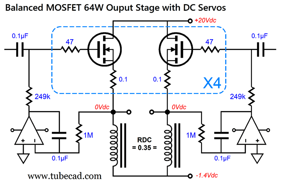
In spite of the 20Vdc power supply, the loudspeaker sees up to 32Vpk output voltage swings (64W into 8-ohm loudspeakers). Each MOSFET idles at 1A, making for 20W of dissipation for each MOSFET, a total of 160W, the same as a conventional class-A output stage would with ±40Vdc power-supply rails. The inductors require an airgap and must be able to sustain 4A of current flow. The trick here is that we use the choke's DC resistance as a current-sense resistor to auto-bias the MOSFET with the two DC servos, a voltage drop of 1.4V divided by 0.35 ohms equals 4A. If we replace the two inductors with a single autoformer, we realize real weight savings, as the autoformer's core does not require an airgap. Ever notice that a single-ended output transformer only delivers half the power that the same sized push-pull transformer does? Well, an autoformer is smaller still. No doubt, the -1.4Vdc negative power-supply rail creates unnecessary concern for many readers. Well, we can make this dissimilar bipolar power supply from a monopolar floating power supply.
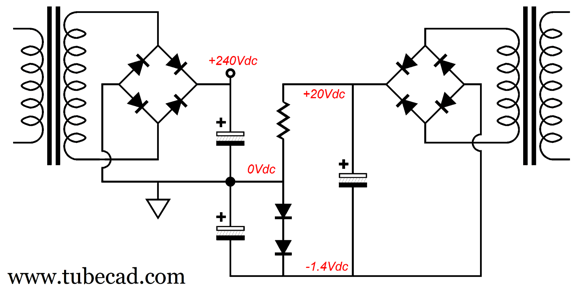
A floating power supply is simply one that makes no direct connection to ground. In the circuit above, ground is at the top of the two-diode string. This trick, however, only works with a balanced output stage. (One floating power supply could be used to power two channels.) The floating power supply could be a switch-mode power supply or something more conventional.
As I want a tube-based frontend to drive the balanced output stage, this is how we arrange the two power supplies:
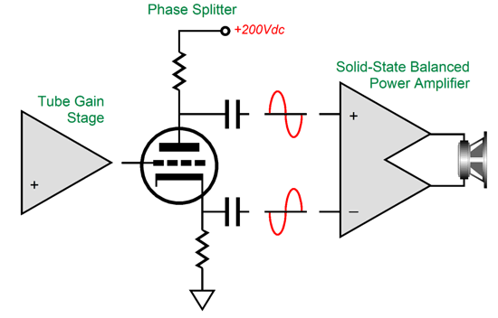
Since I mentioned tubes, here is the design's overview:
My goal is to have the tube-based frontend purposely undo some of the balanced output stage's push-pull harmonics, which means we must use a split-load phase splitter.
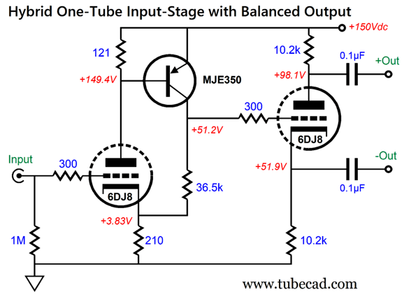
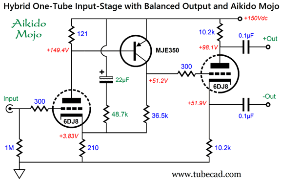
This is the tube-parsimonious version. The input stage is a hybrid affair and does not require an internal coupling capacitor. Since the PNP transistor inverts the phase, the output at its collector is in phase with the input signal. The B+ voltage must be well filtered or, better still, regulated, as the circuit's PSRR is poor. Aikido Mojo to the rescue:
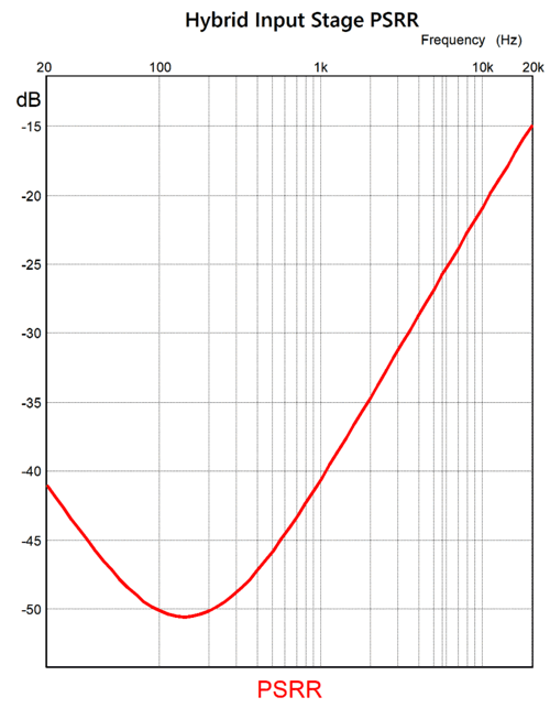
The added capacitor and resistor inject enough power-supply noise to create a deep null centered at 150Hz. (The point is not to eliminate power-supply noise from the two outputs, which is impossible via negative feedback in this topology, but to force an equal amount of power-supply noise at each output of the split-load phase splitter.)
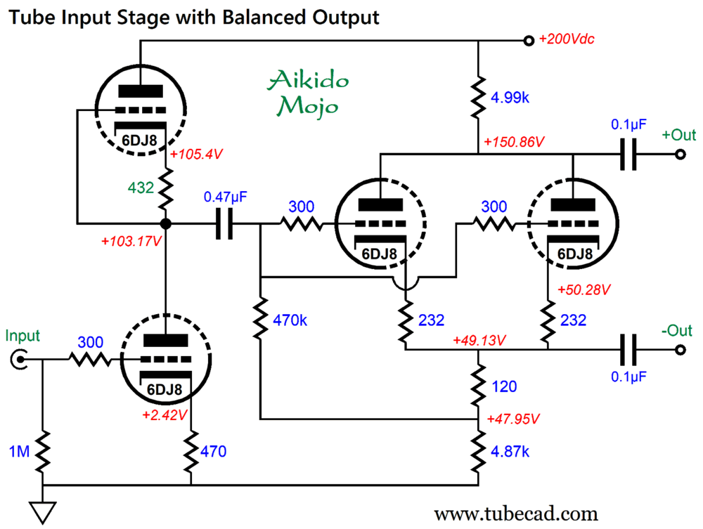
Impressive, but the circuit employs signal negative feedback (the 36.5k resistor) and fails to deliver sufficient tube glory for my taste. Thus, here's the two-tube version.
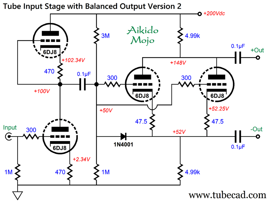
The doubled up triodes in the split-load phase splitter is a feature, as it allows for twice the idle current. Why is that a feature? While MOSFETs are much easier to drive than bipolar transistors, they do present relatively high input capacitance, which is not a big deal at DC and low frequencies, but becomes an issue at high frequencies. It takes current to charge and discharge capacitance quickly. Slew rate (SR) and capacitance (C) are related by the fundamental capacitor charging equations: SR = I/C and I = SR ·C In other words, the higher the current, the higher the slew rate. The following variation allows us to use the same cathode resistor values in the input stage and a smaller-valued internal coupling capacitor:
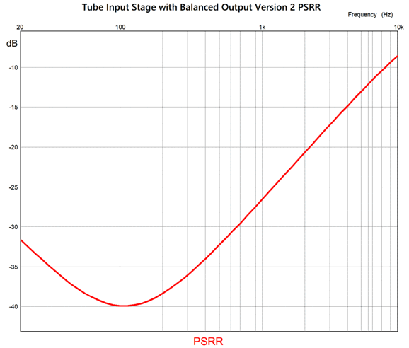
Sadly, the PSRR is not as fine as it was with the hybrid, one-tube version.
Still, without the Aikido Mojo intervention, the PSRR would be far worse.
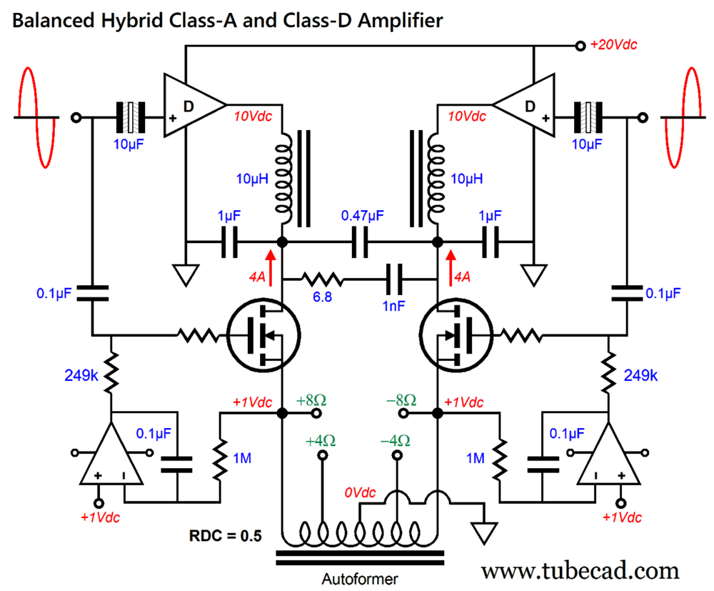
Balanced Hybrid Class-A and Class-D Amplifier
Class-D amplifiers, which run off monopolar power supplies, have outputs at idle resting at half their B+ voltage, which explains why output coupling capacitors are sometimes used (i.e. when the BTL and PBTL configurations are not used).
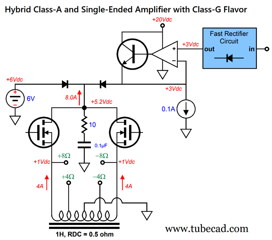
We use this V+/2 feature to our advantage in this design. The two MOSFET dissipate 36W each at idle, a total of 72W, but deliver 64 class-A watts into the loudspeaker. This hybrid design breaks the 50% efficiency rule for push-pull class-A output, as a conventional 64W power amplifier would have to dissipate at least 128W at idle. Mind you, most class-D amplifiers just loaf at idle, with the TPA3255 normally dissipating only 2.5W at idle, but not in this design, as the class-D amplifiers must deliver 4A of total idle current into the MOSFETs. The autoformer allows the loudspeaker to see 32Vpk of output signal from a 20Vdc power supply. Effectively the autoformer functions as a constant-current source, as the 4A current flow remains fairly constant. We could replace the autoformer with two 4A constant-current sources that terminate into a -20Vdc power-supply rail, but they would add 80W of wasted heat dissipation. In contrast, the autoformer only dissipates 8W of heat. (0.5 x 4² = 8) By the way, the assumption here is that the autoformer presents a DC resistance (DCR) of 0.5 ohms, as the two DC servo circuits auto-bias the MOSFETs use the autoformer DCR as a current-sense resistance. By the way, only a few OpAmps can accept an input signals that extends down to (and sometimes slightly beyond) their negative power-supply rail voltage; they are known as "single-supply rail-to-rail input" (RRI) or "ground-sensing" OpAmps. (I could easily devote an entire post to them, as the way this trick is pulled off is fascinating.) In other words, if the OpAmps are going to run off the 20Vdc monopolar power supply, without a negative power-supply rail, then be sure that they qualify as RRI types.
What if you hate the idea of an autoformer with two sets of impedance taps? Why would anyone one do that? For one, it's a novel idea. Second, no high-end $800 autoformers are sold. Who take any audio component (or part) that cost less than $500 seriously? The workaround to this form of audiophile conception-constipation is to replace the autoformer with two constant-current sources. True, we lose the 4-ohm and 8-ohm output taps, but, at the same time, constant-current source are easy to understand and make.
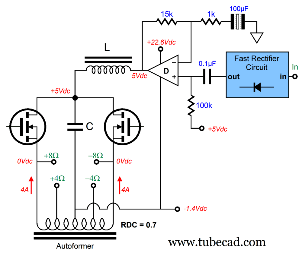
We get the same 64W of output into an 8-ohm loudspeaker, but we halved the dissipation that the constant-current sources would undergo with a fixed -20Vdc power-supply connection, but at the added cost and complexity of having to use twice the number of class-D amplifiers. On the other hand, if we can get class-D amplifiers that can deliver a fixed output voltage other than half the B+ voltage, we could lower the MOSFETs drain voltage to +5Vdc and the constant-current sources negative termination to -5Vdc, thereby halving the balanced class-A output stage's dissipation by half. This design's extravagance and the possibility of a lower class-D amplifier DC output offset voltage made me wonder if we could use only one class-D amplifier instead of four—but we have to bring back the autoformer.
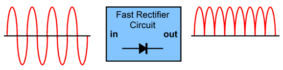
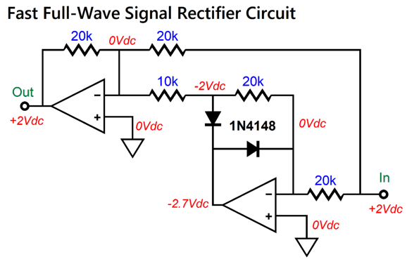
The idea here is that the B+ voltage need only swing up from +5V to around +20V. How this is possible is due to the fast-rectifier circuit. What's that? A fast-rectifier circuit performs a full-wave rectification on an AC input signal.
Fast-Rectifier Circuit
(Sorry for not going from left to right, but then readers in Israel will breathe a sigh of relief.) The input signal is +2V and +2V goes out. Why that is so is due to the mixer circuit on the left seeing the following input signals. 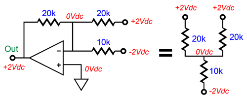
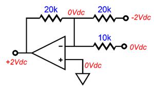
The OpAmp's two inputs must share the same voltage, 0V in this example, which is only possible when the two 20k resistors deliver enough current to cancel the current flow through the 10k resistor. Next, we apply a -2V input signal:
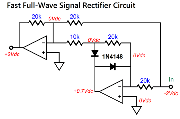
Once again, we get +2V of output, in spite of a negative input voltage. How so? Again, the mixer reveals the answer.
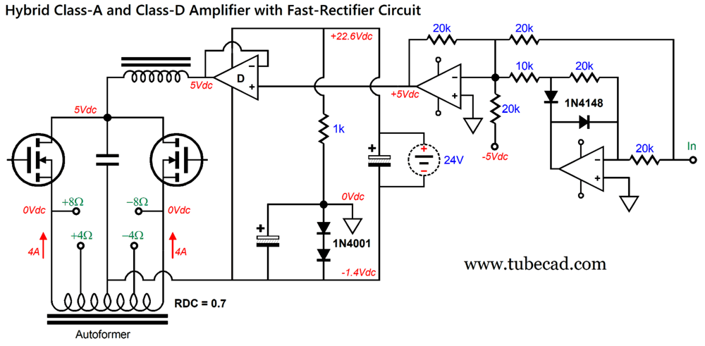
The 10k resistor experiences zero current flow, as no voltage differential exists, so we are left with just an inverting amplifier receiving a -2V input signal. Adding the fast-rectifier circuit to the balanced output stage is easy enough:
Note the low 5V B+ voltage for the MOSFETs and the floating power supply of 24Vdc. The extra 20k resistor that terminates into -5Vdc forces the 5V DC offset on the fast-rectifier circuit. (If the OpAmps run off ±12Vdc, the resistor can terminate into the -12Vdc power-supply rail and its value changed to 48k.) The two 1N4001 rectifiers create the 1.4V bias voltage for the two DC servos that set the auto-bias idle current. The result is that the class-A output stage MOSFETs dissipation drops to 40W. Won't the class-D amplifier dissipate a lot of heat?
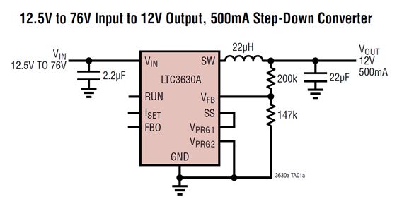
No, not really, as the class-D amplifier functions much like a buck switch-mode voltage regulator. For example, your laptop switch-mode power supply might deliver 20V at 4A, but only feel warm to your touch, in spite of it reducing 160Vdc (in the USA, twice as much in Europe) down to 20Vdc. Where did the 160Vdc come from? The 115Vac wall voltage is rectified to 160V, and the buck switch-mode power supply reduces it to 20Vdc. Here is an example of a typical buck regulator, the LT3630A.
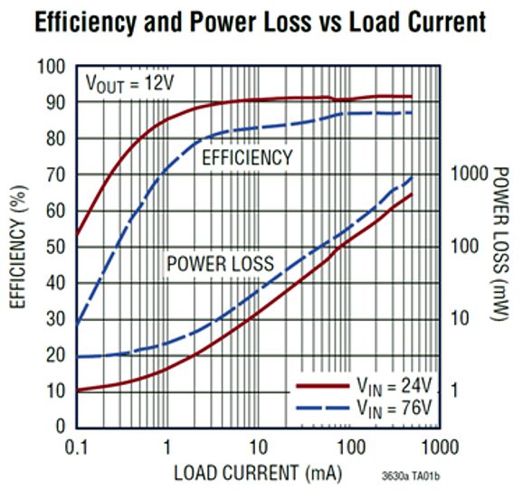
Here is the LT3630A's efficiency graph.
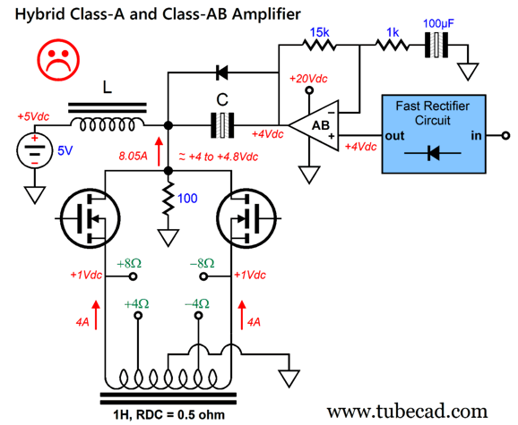
The magic lies in the switching power supply internal MOSFETs producing square-waves, being either fully on or fully off, so no voltage drop during high current conduction and no current conduction during high-voltage drop. The same holds largely true for the class-D amplifier's MOSFETs. The big problem with this design is that the class-D amplifier must allow for the 5V DC offset voltage at its output, which might be tough with most class-D amplifier ICs, as they usually contain voltage-centering and protection circuitry to prevent the output from straying from half of the B+ voltage. One thought I had was that of using a 5Vdc switch-mode power supply and a class-AB power amplifier. But unlike the class-D amplifier version, the class-AB amplifier would attach via a large-valued coupling capacitor, while the MOSFET output stage attaches to the 5Vdc power supply via an inductor.
The class-AB amplifier's gain is set by the 15k and 1k negative-feedback-loop resistors, i.e. 1:16, which matches the tube-based frontend with 6DJ8 tubes. The inductor and capacitor must be huge in value. How huge? If we shoot for a Linkwitz-Riley 2nd-order low-pass filter alignment with a Q of 0.5 and a 5Hz cutoff frequency, the inductor must be 6.4H; the capacitor, 160µF. One way to think about it is to imagine that the inductor attaches to a 20Vdc power supply and the capacitor terminates to ground, while the class-AB amplifier is removed from the circuit. The balanced output would remain the same. The only reason the class-AB amplifier is needed is to give the MOSFET enough voltage headroom to allow +16Vpk voltage swings. Is this a Musk-Prize worthy idea? No.
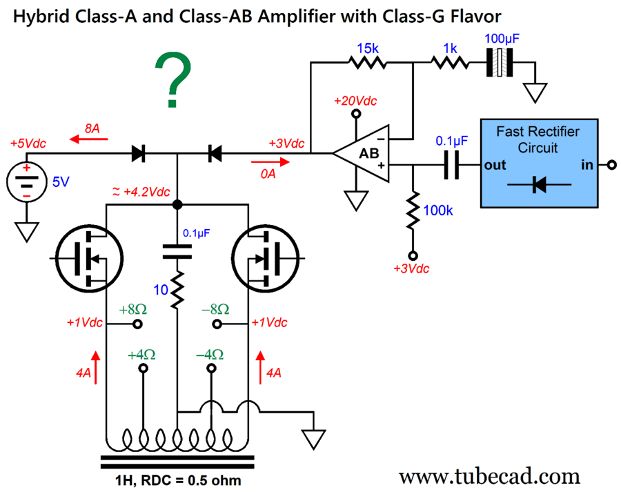
The 5Vdc power supply continuously delivers 8.05A of current at idle. That part works. What fails is that the inductor does not see sine-waves from the class-AB amplifier, but only positive rectified pulses, which given enough time, will undo the inductor's high output impedance. New idea: lose the inductor and capacitor, but add two diodes.
No big inductor, no big capacitor. Excellent. The way it works is that once the class-AB amplifier's goes a fraction of a volt over 5Vdc, the amplifier replaces the 5V power supply and must supply all 8A of current. The two rectifiers should be of the super-fast types, such as the FRED and SMPS ultra-fast rectifiers. The question mark denotes my concern that the transition might prove too abrupt. At idle, the class-AB amplifier draws only its idle current, say 100mA; but once the music commences, the amplifier must deliver 8A of current flow. More damning, is the 0.1µF output-coupling capacitor from the fast-rectifier circuit, as it will charge up from repeated positive pulses, thereby causing the class-AB amplifier's DC offset to fall. Newer idea: replace the class-AB amplifier with a single-ended amplifier that idles at 100mA and eliminate the coupling capacitor. In other words, we return to the forced DC offset from the fast-rectifier circuit.
Since the pull-up amplifier only sees positive pulses, the single-ended output stage makes sense. At idle, the NPN transistor only dissipates 1.7W; but once its output voltage exceeds 6V, its instantaneous dissipation jumps to 112W! At full output, its dissipation falls to about 16W. I am going to call it quits on this topic, but I have many more apples to examine in the future.
MORE
More Broskie Amplitude-Staggered Active Crossovers
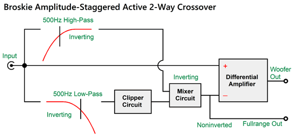
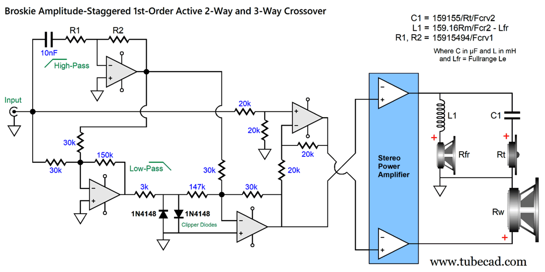
What my last post didn't do was show how the crossover could be used in a 1st-order staggered three-way active loudspeaker. The key word in that last sentence was "staggered." The idea here is that a two-way loudspeaker based on a fullrange driver and tweeter delivers great sound at low volume, but gets into trouble at high SPLs, as the fullrange driver gets hammered by the powerful bass, and the tweeter sees too much low-frequency signal due to its shallow cutoff slope. By adding a woofer and my BASAC crossover the woofer and a 500Hx high-pass filter kicks in and the tweeter sees cascading slopes, thereby relieving and protecting the fragile fullrange driver and tweeter.
And, yes, the top amplifier could be tube-based, while the bottom amplifier is solid-state, perhaps a class-D amplifier. In other words, this is nominally a two-way 1st-order loudspeaker that automatically shifts into a three-way when needed.
Music Recommendation: Yosi Horikawa's Impulse Let's be frank: the hobby of audio is often a lonely, singular affair, as so few are willing to sit still, silently, without a pixel-enhanced device in hand. Few spouses share the hobby. Most friends deride the expense and effort. All of which conspires to condemn the audiophile to a solitary enjoyment of his system. His expensive audio cables chain him to one room in his home. Alone he sits, as cleanly–recorded music fills the room.
Outside, the wind blows, storms thunder, birds sing, raindrops pitter-patter, ocean waves roll and crash… Well, this album brings nature into your home. Of course, there is a long history of nature recordings, but none equal this album's ability to convincingly refabricate the scale and majesty of nature. For example, the tenth track, "Underwater" actually prompted my instinctive holding of my breath as I heard and felt a huge wave crash above me. Yes, above me. (I would love to know how he achieves the sonic miracle of hyper tall and above-head stereo imaging.) Mind you, music blends and mixes with the nature sounds. As I listened to album, I wondered what Gustav Mahler would have thought of it, as he thought that his Symphony No. 3 had encompassed the entire sound and evolution of nature—telling a friend after his friend had commented on the beauty of nature in the countryside, "There, you have a kind of program, a sample of how I make music—always and everywhere only the sound of nature!" //JRB
Did you enjoy my post? Do you want to see me make it to post 1,000? If so, think about supporting me at Patreon.
Adobe AI Summary: The central idea is to exploit class-D amplifiers’ tolerance for low-impedance and capacitive loads in hybrid, transformer-coupled, and active-speaker designs. Core amplifier concepts
Hybrid class-A/class-D output stages
Autoformers and inductive loading
More ambitious hybrid variants
Input-stage ideas
|
I know that some readers wish to avoid Patreon, so here is a PayPal button instead. Thanks. John Broskie
John Gives
Special Thanks to the Special 89 To all my patrons, all 89 of them, thank you all again. I want to especially thank
I am truly stunned and appreciative of their support. In addition I want to thank the following patrons:
All of your support makes a big difference. I would love to arrive at the point where creating my posts was my top priority of the day, not something that I have to steal time from other obligations to do. The more support I get, the higher up these posts move up in deserving attention.
If you have been reading my posts, you know that my lifetime goal is reaching post number one thousand. I have 352 more to go. My second goal was to gather 1,000 patrons. Well, that no longer seems possible to me, so I will shoot for a mighty 100 instead. Thus, I have just 11 patrons to go. Help me get there. Thanks.
New URL of the GlassWare Store website |
||||









| www.tubecad.com Copyright © 1999-2026 GlassWare All Rights Reserved |